Two-Wattmeter and Three-Wattmeter Methods
Measuring power in three-phase circuits is crucial for monitoring energy consumption and ensuring the efficient operation of electrical systems. Two primary methods for this measurement are the two-wattmeter method and the three-wattmeter method. The choice between these methods depends on the configuration of the three-phase system, specifically whether it is a three-wire or a four-wire system, and the nature of the load.
The Two-Wattmeter Method
The two-wattmeter method is a widely used and versatile technique for measuring the total power in a three-phase, three-wire system. A key advantage of this method is its applicability to both balanced and unbalanced loads, and for both star (Y) and delta (Δ) connected loads, without the need for a neutral wire.
Circuit Connection:
In this method, the current coils of two wattmeters are inserted into any two of the three lines (e.g., lines A and C). The potential coil of each wattmeter is then connected between the line containing its current coil and the third line (line B).
For a Star-Connected Load:
- Wattmeter 1 (W1): Current coil in line A, potential coil between line A and line B.
- Wattmeter 2 (W2): Current coil in line C, potential coil between line C and line B.
For a Delta-Connected Load: The connection remains the same, with the wattmeters connected to two lines and the third line serving as the common potential reference.
Principle and Power Calculation:
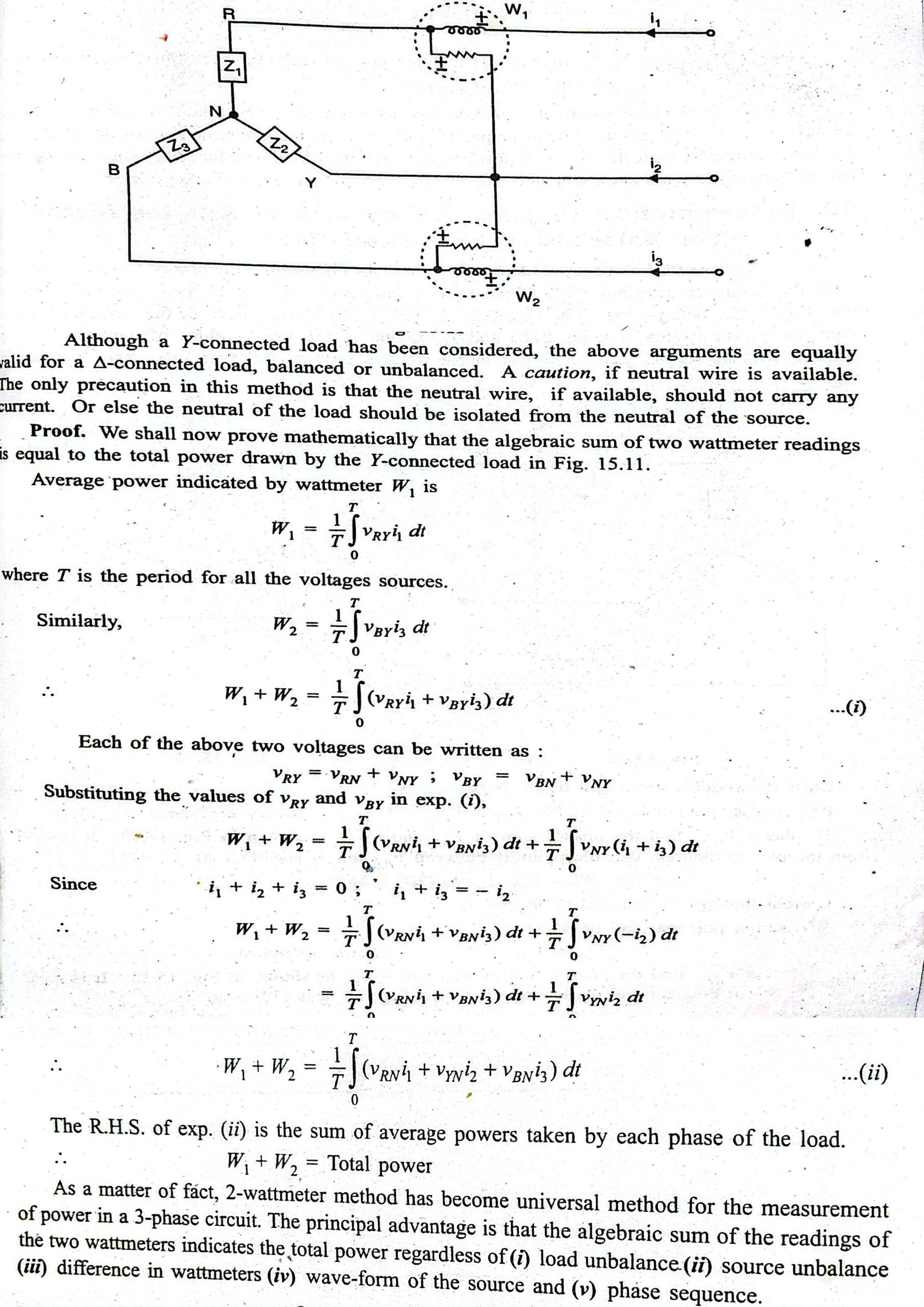
Based on Blondel’s Theorem, which states that, for a system with ‘n’ conductors, ‘n-1’ wattmeters are required to measure the total power, a three-phase, three-wire system requires two wattmeters.
The total instantaneous power in the three-phase circuit is the sum of the instantaneous powers in each phase. The two-wattmeter method cleverly measures this total power by taking the algebraic sum of the readings of the two wattmeters.
The total average power (Ptotal) consumed by the load is given by:
Ptotal =W1+W2
Where W1 and W2 are the readings of the two wattmeters. It’s important to note that under certain power factor conditions, one of the wattmeter readings can be negative. In such cases, the algebraic sum still holds true.
Phasor Diagram and Power Factor Determination (for balanced loads):
For a balanced load, the readings of the two wattmeters are:
W1 =VLILcos (30∘−ϕ); W2 = VLILcos(30∘+ϕ)
Where:
- VL is the line voltage.
- IL is the line current.
- ϕ is the phase angle of the load (the angle between the phase voltage and phase current).
From these two readings, the power factor of the load can be determined:
tan(ϕ) = 3W1+W2W1−W2
And the power factor is cos(ϕ).
The relationship between the wattmeter readings and the power factor provides valuable insights:
- Unity Power Factor (cos(ϕ)=1, ϕ=0∘): W1=W2
- Power Factor of 0.5 lagging (cos(ϕ)=0.5, ϕ=60∘): One wattmeter (W2) reads zero.
- Power Factor less than 0.5 lagging: One wattmeter (W2) will show a negative reading.
Ptotal =W1+W2 ………………… Algebraic sum
Advantages:
- Applicable to both balanced and unbalanced loads in a three-wire system.
- Cost-effective as it requires only two wattmeters.
- Can be used for both star and delta connected loads.
- Allows for the determination of the power factor in balanced load conditions.
Disadvantages:
- Not suitable for three-phase, four-wire systems.
The Three-Wattmeter Method
The three-wattmeter method is used for measuring power in a three-phase, four-wire system. It can also be applied to a three-wire system, but it is the primary method when a neutral wire is present, especially in cases of unbalanced loads where a neutral current may flow.
Circuit Connection:
In this method, a wattmeter is placed in each of the three phases. The current coil of each wattmeter is connected in series with its respective line (A, B, and C). The potential coils are all connected between their respective lines and the common neutral wire.
- Wattmeter 1 (W1): Current coil in line A, potential coil between line A and the neutral.
- Wattmeter 2 (W2): Current coil in line B, potential coil between line B and the neutral.
- Wattmeter 3 (W3): Current coil in line C, potential coil between line C and the neutral.
Principle and Power Calculation:
Each wattmeter measures the power consumed by the individual phase to which it is connected. The total power in the circuit is simply the arithmetic sum of the readings of the three wattmeters.
The total average power (Ptotal) is given by:
Ptotal=W1+W2+W3
This method is accurate for both balanced and unbalanced loads in a four-wire system because it directly measures the power in each phase, and the presence of the neutral connection ensures a correct voltage reference for each potential coil.
Advantages:
- The most accurate method for all types of loads (balanced and unbalanced) in a four-wire system.
- Provides the measurement of power consumed in each phase individually, which can be useful for load balancing analysis.
Disadvantages:
- Requires three wattmeters, making it more expensive than the two-wattmeter method.
- The setup is more complex due to the increased number of instruments.
Comparison Summary: Two-Wattmeter vs. Three-Wattmeter Method
| Feature | Two-Wattmeter Method | Three-Wattmeter Method |
| Number of Wattmeters | Two | Three |
| Applicability (System) | Three-phase, three-wire systems. | Primarily for three-phase, four-wire systems. |
| Applicability (Load) | Balanced and unbalanced loads. | Balanced and unbalanced loads. |
| Cost | More economical. | More expensive. |
| Complexity | Simpler connections. | More complex connections. |
| Individual Phase Power | Does not directly measure power in each phase. | Measures the power in each phase individually. |
| Power Factor Determination | Can be calculated for balanced loads. | Not directly calculated from the sum of readings. |
In conclusion, the two-wattmeter method is a versatile and economical choice for measuring power in the vast majority of three-phase, three-wire industrial and commercial applications. The three-wattmeter method is essential for accuracy in three-phase, four-wire systems, particularly when dealing with unbalanced loads that can result in current flow through the neutral conductor.
Unbalanced Load in a Four-Wire Star Connected System
In a three-phase electrical system, an ideal scenario involves a balanced load, where the impedance and power factor are identical across all three phases. However, in real-world applications, this perfect equilibrium is often unattainable, leading to what is known as an unbalanced load. When such an imbalance occurs in a four-wire star (or wye) connected system, it gives rise to unique characteristics, primarily the flow of current through the neutral wire. This comprehensive overview explores the principles, calculations, and implications of an unbalanced four-wire star-connected load.
The Crucial Role of the Neutral Wire
The four-wire star connection consists of three phase conductors (L1, L2, and L3) and a neutral conductor (N), all originating from a common star point at the source. In a balanced system, the phasor sum of the currents in the three phases is zero. Consequently, no current flows through the neutral wire.
However, when the loads connected to the different phases are unequal in impedance or have different power factors, the system becomes unbalanced. This inequality disrupts the symmetrical flow of current, and the phasor sum of the phase currents is no longer zero. This resultant current, known as the neutral current, finds its return path through the neutral conductor. Therefore, the primary function of the neutral wire in an unbalanced star-connected system is to provide a path for this imbalance current, thereby preventing the star point of the load from “floating” and ensuring that the phase voltages across the loads remain relatively constant and equal to the source phase voltages.
Calculating Currents in an Unbalanced System
To analyze an unbalanced four-wire star-connected system, it is essential to calculate the line currents (which are the same as the phase currents in a star connection) and the neutral current.
Unbalanced Load in a Four-Wire Star Connected System: A Deep Dive
In a three-phase electrical system, an ideal scenario involves a balanced load, where the impedance and power factor are identical across all three phases. However, in real-world applications, this perfect equilibrium is often unattainable, leading to what is known as an unbalanced load. When such an imbalance occurs in a four-wire star (or wye) connected system, it gives rise to unique characteristics, primarily the flow of current through the neutral wire. This comprehensive overview explores the principles, calculations, and implications of an unbalanced four-wire star-connected load.
Line Current Calculation
Assuming the phase voltages are balanced (equal in magnitude and displaced by 120°), the line current for each phase can be calculated using Ohm’s Law. Let the phase voltages be:
- VAN = ∠ 0°
- VBN = ∠ -120°
- VCN = ∠ 120°
Where is the magnitude of the phase voltage.
If the impedances of the unbalanced loads are , , and for phases A, B, and C respectively, the line currents are:
- IA = ZAVAN
- IB=ZBVBN
- IC=ZCVCN
These calculations will yield the magnitude and phase angle of each line current. Due to the differing impedances, the magnitudes and phase angles of the line currents will be unequal.
Neutral Current Calculation
The neutral current () is the phasor sum of the three line currents. According to Kirchhoff’s Current Law, the algebraic sum of currents entering a junction is zero. Applying this to the star point of the load:
+IB+IC+IN = 0
Therefore, the neutral current is:
= − (IA+IB+IC)
This calculation involves vector addition of the three line currents. The magnitude and phase angle of the neutral current will depend on the degree of imbalance in the system.
Power Calculation in an Unbalanced System
In an unbalanced system, the total power cannot be calculated by simply multiplying the total current by the total voltage, as is common in balanced systems. Instead, the power in each phase must be calculated individually, and then summed to find the total power.
The total active power (P), reactive power (Q), and apparent power (S) are calculated as follows:
- Total Active Power (Ptotal): The sum of the active power in each phase. = PA+PB+PC Where = VAN⋅IA⋅cos(θA), = VBN⋅IB⋅cos(θB), and = VCN⋅IC⋅cos(θC). is the phase angle difference between the voltage and current in each phase.
- Total Reactive Power (Q_total): The algebraic sum of the reactive power in each phase. = QA+QB+QC Where =VAN⋅IA⋅sin(θA), = VBN⋅IB⋅sin(θB), and =VCN⋅IC⋅sin(θC).
- Total Apparent Power (Stotal): The vector sum of the total active and reactive powers. = Ptotal2 + Qtotal2
It is important to note that the total apparent power in an unbalanced system is not simply the sum of the individual apparent powers of the phases.
Visualizing with Phasor Diagrams
Phasor diagrams are an invaluable tool for visualizing the relationships between voltages and currents in an unbalanced four-wire star-connected system.
- Voltage Phasors: In a balanced supply, the phase voltage phasors (, , and ) will be of equal length and displaced from each other by 120°.
- Current Phasors: The line current phasors (, , and ) will have different lengths and will be displaced from their respective voltage phasors by different angles, depending on the impedance of each phase.
- Neutral Current Phasor: The neutral current phasor () is found by graphically adding the three line current phasors (tip-to-tail). The resulting phasor from the origin to the tip of the final current phasor represents the neutral current. In a perfectly balanced system, the three current phasors would form a closed triangle, resulting in a zero-length neutral current phasor.
Implications of Unbalanced Loads
Unbalanced loads in a four-wire star-connected system can lead to several undesirable effects:
- Overloading of the Neutral Conductor: A significant neutral current can cause the neutral conductor to overheat if it is not sized appropriately.
- Increased Losses: The presence of neutral current contributes to additional I²R losses in the system, reducing overall efficiency.
- Voltage Fluctuations: Severe unbalance can cause variations in the phase voltages, affecting the performance and lifespan of connected equipment.
- Harmonics: Unbalanced loads, particularly non-linear loads, can introduce harmonic currents into the system, which can further exacerbate the problem.