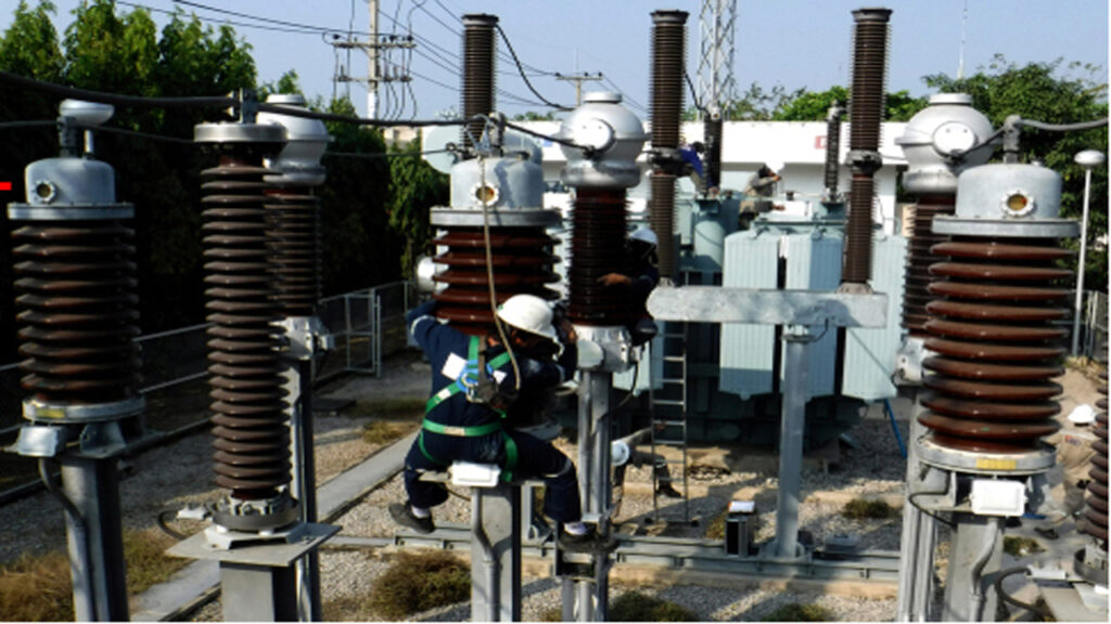
Transformers Definition:
An electrical transformer is a passive component that transfers electrical energy from one circuit to another through electromagnetic induction without a change in frequency.
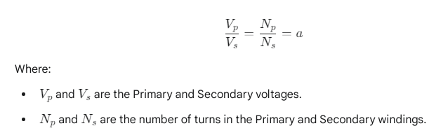
Its primary function is to change the voltage level (either increase or decrease it) of an alternating current (AC) supply. The fundamental relationship between the voltages and the windings (coils) is defined by the Turns Ratio ()
Types Transformer:
According to operation:-
- Step up Transformer
- Step down Transformer
- One to One Transformer
According to Construction of core:-
- Core type Transformer
- Sell type Transformer
- Spiral core type Transformer
According to Cooling System:-
- Natural Cooled Transformer
- Air Cooled Transformer
- Oil Cooled Transformer (Self cooled & water cooled).
According to Apply System:-
- Power Transformer
- Distribution Transformer
- Auto Transformer
- Instrument Transformer (Current Transformer & Potential Transformer).
According to Set up System:-
- Indoor type Transformer
- Outdoor type Transformer
- Pole mounted type Transformer
According to Frequency:-
- Audio Frequency Transformer
- Radio Frequency Transformer
According to Phase:-
- Single Phase Transformer
- Three Phase Transformer
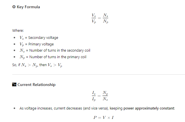
Step-Up Transformer:
A Step-Up Transformer is an electrical device designed to increase (step up) the voltage of an alternating current (AC) source from its primary side to its secondary side.
Basic Principle
A step-up transformer works on the principle of electromagnetic induction and Faraday’s Law. It consists of two coils:
- Primary coil – connected to the input voltage (lower voltage).
- Secondary coil – provides the output voltage (higher voltage).
If the number of turns in the secondary coil is greater than the number in the primary coil, the transformer steps up the voltage.
Applications of Step-Up Transformers
- Power transmission: Used in power plants to raise voltage for transmission over long distances (reduces losses).
- X-ray machines: Require high voltage to produce X-rays.
- Microwave ovens: Use high voltage for magnetron operation.
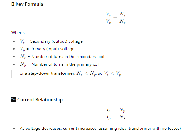
Step down Transformer:
A step-down transformer is a type of electrical transformer used to decrease voltage from the primary (input) side to the secondary (output) side, while increasing current proportionally to conserve power (ideally).
Basic Principle:
Like all transformers, a step-down transformer operates on the principle of electromagnetic induction, using mutual induction between two coils (primary and secondary). The voltage change is determined by the ratio of the number of turns in each coil.
Applications of Step-Down Transformers
- Mobile chargers: Convert 220V or 110V AC to 5V or 9V DC.
- Household appliances: Power devices requiring lower voltages.
- Distribution transformers: Reduce high transmission voltages (like 11kV) to usable levels (e.g., 230V or 120V).
- Electronics: Used in adapters and power supplies.
One to One Transformer:
A one-to-one transformer is a type of transformer where the number of turns in the primary coil is equal to the number of turns in the secondary coil, resulting in no change in voltage or current (ideally). It’s also called a unity transformer or isolation transformer. Even though the voltage doesn’t change, using a one-to-one transformer improves safety, reduces noise, and can help meet electrical codes in sensitive environments.
Purpose and Applications:
The main reason to use a one-to-one transformer is electrical isolation — to separate two circuits electrically while allowing power transfer.
✅ Common Uses:
- Isolation for safety: Protects devices or people from electric shock.
- Noise reduction: Helps eliminate ground loops and reduce electrical noise in sensitive equipment.
- Medical equipment: To isolate patient-connected devices.
- Audio systems: Isolates signal lines to prevent hum and interference.
Note
The term “One-to-One Transformer” is not a standard or widely recognized category within the field of deep learning. The search results do not explicitly define a “One-to-One” transformer model.
Core type Transformer:
A Core-Type Transformer is a type of transformer construction where the windings (coils) surround the magnetic core. This design is prevalent in electrical engineering, particularly for high-voltage applications like power transmission and distribution.
Construction and Features
- Core Structure: The core forms a rectangular frame (sometimes called the “mouth” type for single-phase) and is typically made of thin, laminated silicon steel sheets to reduce eddy current and hysteresis losses.
- For a single-phase core-type transformer, the core usually consists of two vertical sections called limbs and two horizontal sections called yokes.
- For a three-phase core-type transformer, the core commonly has three limbs.
- The core laminations are often L-shaped strips stacked to prevent continuous joints.
- Winding Placement: The primary and secondary windings, which are typically cylindrical or concentric coils, are wound around the two limbs of the core.
- To minimize the amount of insulating material required and reduce leakage flux, the low-voltage (LV) winding is placed closer to the core, and the high-voltage (HV) winding is wound concentrically around the LV winding.
- Half of the primary and secondary windings may be placed on each limb.
- Magnetic Circuit: It provides a single, low-reluctance path for the magnetic flux.
Working Principle
The core-type transformer operates based on the principle of mutual electromagnetic induction.
- AC Voltage Application: When an alternating current (AC) voltage is applied to the primary winding, it produces a constantly changing magnetic flux (ϕ) that is confined to the core.
- Flux Linkage: This changing flux flows through the core and links with both the primary and secondary windings.
- Induced EMF: According to Faraday’s Law of Induction, this changing magnetic flux induces an electromotive force (EMF) in both the primary (Ep) and secondary (Es) windings.
- The magnitude of the induced EMF is proportional to the rate of change of flux and the number of turns in the respective winding.
- Voltage Transformation: The ratio of the primary voltage to the secondary voltage is nearly equal to the ratio of the number of turns in the primary winding (Np) to the number of turns in the secondary winding (Ns).
Vs/ Vp ≈ Ns/ Np
Core-Type vs. Shell-Type Transformer Comparison
| Aspect | Core-Type Transformer | Shell-Type Transformer |
| Winding & Core | Windings surround the core (Core inside the windings). | Core surrounds the windings (Windings inside the core/shell). |
| Core Limbs | Two limbs and two yokes (for single-phase). | One central limb and two outer limbs. |
| Magnetic Circuits | One magnetic circuit. | Two magnetic circuits. |
| Winding Type | Concentric or Cylindrical winding. | Sandwich or Disc winding. |
| Cooling | Better natural cooling as windings are on the outside. | Natural cooling is less efficient as windings are surrounded by the core. |
| Applications | Favored for High-Voltage applications (e.g., power distribution). | Preferred for Low-Voltage, high-output applications. |
| Maintenance | Easier to dismantle and maintain since fewer windings need to be removed. | More difficult to access windings for maintenance. |
Advantages:
- Simple design and construction.
- Good for high-voltage applications.
- Easy to cool using air or oil.
- Easier to insulate primary and secondary windings.
Disadvantages:
- Magnetic leakage is higher compared to shell type.
- Requires more copper for windings (due to longer mean turn length).
Shell-Type Transformer:
A shell-type transformer is a type of transformer in which the core surrounds the windings. Unlike the core-type transformer, where windings are wrapped around the core limbs, in a shell-type transformer, the windings are placed in the center limb, and the core has two outer limbs, forming a closed magnetic circuit around the windings.
Structure of a Shell-Type Transformer
- The core is shaped like a double window or an “E-I” configuration.
- It has three limbs:
- The central limb holds both the primary and secondary windings, often interleaved for better magnetic coupling.
- The two outer limbs complete the magnetic path.
- The core surrounds the windings, which improves magnetic shielding and reduces leakage flux.
Construction and Working
- Core Structure: A single-phase shell-type transformer typically consists of three limbs and two yokes. It is characterized by having the core material surround the windings, which gives it its “shell” name.
- Laminations: The core is often constructed using E and I-shaped or U and T-shaped laminations of thin silicon steel to minimize eddy current losses.
- Winding Placement: Both the primary and secondary windings are placed on the central limb.
- Winding Type: The windings are typically layered in a technique called sandwich or disc winding, where subsections of the low-voltage (LV) and high-voltage (HV) windings are placed alternately on the central limb. This arrangement increases magnetic coupling and reduces leakage flux.
- The central limb usually has a cross-sectional area that is twice the area of each outer limb.
- Magnetic Circuit: It has a dual magnetic circuit. The main magnetic flux () flows through the central limb and then divides into two paths ( each) through the two outer limbs before completing the circuit. This results in a shorter magnetic path and thus requires a smaller magnetizing current.
- Overall Design: The core acts as a protective shell around the windings.
Advantages:
- Better magnetic coupling → higher efficiency.
- Lower leakage flux.
- Compact design for large power ratings.
- Better mechanical strength → useful in short-circuit conditions.
- Less electromagnetic interference.
Disadvantages:
- More complex construction.
- More core material required (costlier than core-type).
More difficult cooling compared to core-type (especially natural cooling).
Applications of Shell-Type Transformers:
- Power electronic devices.
- Audio transformers.
- Welding transformers.
- Low-voltage, high-current transformers.
- Precision measurement equipment.
Power Transformer
A power transformer is a static electrical apparatus with two or more windings that, by electromagnetic induction, transfers electrical energy between two or more circuits. It is primarily used in power generation stations and transmission substations to transform voltage and current, typically at the beginning of the electrical grid, for the purpose of efficient long-distance power transmission.
- Key Function: To step up (increase) voltage for transmission or step down (decrease) voltage in transmission substations.
- Characteristic: Designed to operate at or near full-load for an extended period, with maximum efficiency at full load
Distribution Transformer
A distribution transformer, or service transformer, is a transformer that provides the final voltage reduction in the electric power distribution system. It steps down the high voltage of the distribution lines to the lower voltage level required by the customer (homes, businesses, etc.).
- Key Function: To step down the distribution voltage to a utilization voltage suitable for end-users.
- Characteristic: Energized 24 hours a day but typically operates at variable loads (often less than full load). It is designed to have maximum efficiency at loads between half and three-quarters of its full capacity to minimize energy loss over time.
Auto Transformer
An autotransformer is an electrical transformer that has only one winding which serves as both the primary and secondary winding.
- Key Function: To change the voltage level between two circuits where the voltage ratio is relatively small.
- Characteristic: Unlike a standard transformer (which has separate windings), the primary and secondary circuits are electrically connected as well as magnetically coupled. This design results in a smaller, lighter, and cheaper unit compared to a two-winding transformer of the same rating, but it does not provide electrical isolation between the circuits.
Instrument Transformer
Instrument transformers are high-accuracy electrical devices used to safely isolate and transform high voltages or high currents to lower, standardized, measurable values. This allows standard, low-power measuring instruments and protective relays to be used in high-voltage and high-current circuits.
The two most common types are:
- Current Transformer (CT): Steps down the current to a measurable level (e.g., a ratio of 100:5 A). It is connected in series with the primary circuit.
- Potential Transformer (PT) or Voltage Transformer (VT): Steps down the voltage to a standardized low voltage (e.g., 120 V). It is connected in parallel (shunt) across the high-voltage circuit.
Single-Phase Transformer
A single-phase transformer is designed to operate on a single-phase AC power system.
- Key Function: To transfer single-phase AC power and change its voltage level.
- Characteristic: It typically consists of a magnetic core and one primary winding and one secondary winding. They are commonly used for residential and small commercial loads.
Three-Phase Transformer
A three-phase transformer is an apparatus that transforms three phases of AC power simultaneously, either by using three separate single-phase transformers (a bank) or by using a single unit with three sets of primary and secondary windings on a common three-limbed core.
- Key Function: To transform three-phase AC power and change its voltage level for transmission, distribution, and industrial loads.
- Characteristic: It has ** three primary windings and three secondary windings**, spaced electrically 120 degrees apart, for use in high-power industrial and utility applications where three-phase power is required for efficiency and continuous operation.