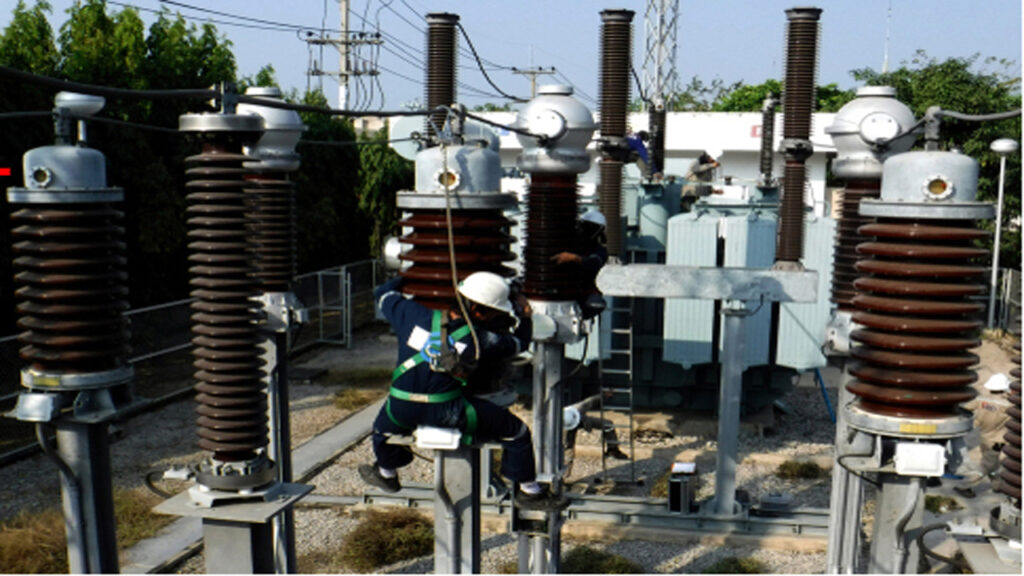
Transformer Losses:
A transformer is a static device that transfers electrical energy from one circuit to another through electromagnetic induction.
However, during energy conversion, some losses occur which reduce its efficiency.
Transformer Losses or Energy losses in a transformer are primarily categorized into two types: core losses (also known as iron losses or no-load losses) and copper losses (also known as winding losses or load losses). (a) Core Losses (Iron Losses)
Core Losses (Pcore):
- These occur in the core of the transformer due to alternating magnetic flux.
- Core losses are constant for a given supply voltage and frequency.
- Core losses are important in total Transformer Losses
Core losses consist of Hysteresis Loss and Eddy Current Loss.
Hysteresis Loss:
Transformer Losses at this loss is due to the repeated magnetization and demagnetization of the transformer core as the alternating current flows. The energy consumed in aligning the magnetic domains in the core material is dissipated as heat. It can be minimized by using silicon steel, which has a low hysteresis coefficient.
- Due to the magnetization and demagnetization of the core in each cycle.
- Depends on the material and frequency.
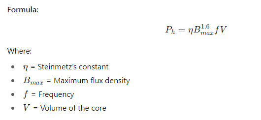
Minimization: Use cold rolled grain-oriented (CRGO) silicon steel to reduce hysteresis loss.
Eddy Current Loss:
The alternating magnetic flux in the core induces electromotive forces (EMFs), which in turn cause circulating currents called eddy currents within the core. These currents produce heat (I2R loss) and represent a waste of energy. To minimize this loss, the core is constructed from thin, laminated sheets of steel that are insulated from each other.
- Caused by circulating currents induced in the core due to changing flux.
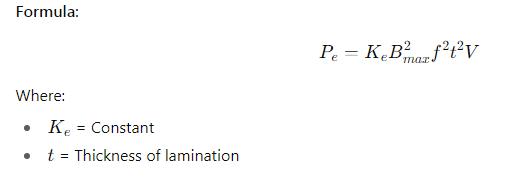
Minimization: Use thin laminated sheets insulated from each other.
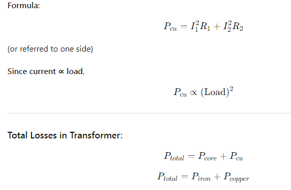
Copper Losses (Pcu)
These losses occur in the primary and secondary windings of the transformer due to the resistance of the copper wire. As current flows through these windings, heat is generated according to the formula P = I2R. Copper losses are variable and depend on the square of the current flowing through the windings, which is directly proportional to the load on the transformer.
- Occur due to the resistance of the primary and secondary windings.
- Vary with the load current.
Transformer Dielectric Loss
Dielectric loss occurs in the insulating materials of a transformer, primarily in the transformer oil and the solid insulation of the windings.
Ideally, the insulation of a transformer should act as a perfect capacitor, storing energy without any loss. However, no insulating material is perfect. When an alternating voltage is applied across the insulation, the electric field causes the dipoles within the material to continuously reorient themselves. This molecular motion creates friction and heat, which is a form of energy loss.
Key characteristics of dielectric loss:
- It’s a very small loss compared to core or copper losses.
- It’s dependent on the applied voltage and the quality of the insulation.
- Deterioration of insulation due to aging or contamination increases these losses.
- This loss is often measured by the dissipation factor or tan delta test, which indicates the condition of the insulation.
Transformer Stray Losses
Stray losses are miscellaneous losses primarily caused by the leakage flux of the transformer. When the transformer is under load, not all the magnetic flux created by the primary winding links with the secondary winding. This unlinked flux is called leakage flux.
This leakage flux, being an alternating magnetic field, induces eddy currents in any surrounding conductive parts that are not part of the main electrical circuit. These eddy currents produce heat, resulting in energy loss.
Common areas where stray losses occur:
- The Transformer Tank: The leakage flux can induce significant eddy currents in the steel walls of the transformer tank.
- Core Clamps and Structural Steel: Metal components used to clamp the core and support the structure can have eddy currents induced in them.
- Large Conductors: In high-current transformers, eddy currents can even be induced within the main winding conductors themselves, leading to additional losses.
Key characteristics of stray losses:
- They are load-dependent, increasing with the square of the load current ().
- They are more significant in larger transformers with higher leakage flux.
- Careful design, such as using magnetic shunts or non-magnetic steel for certain parts, can help to minimize stray losses.
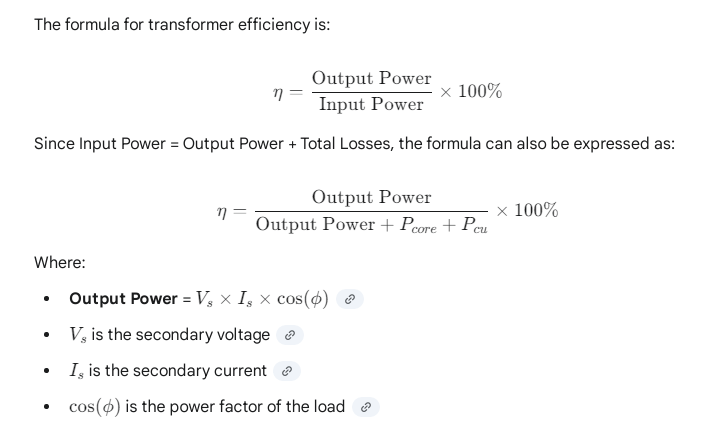
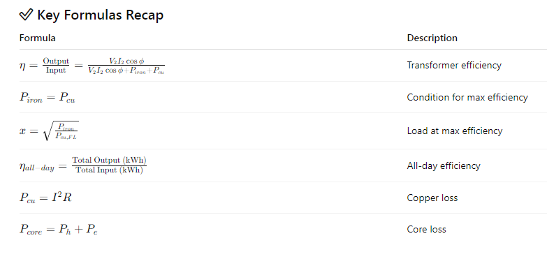
Efficiency of a Transformer (η)
The efficiency of a transformer is the ratio of the output power to the input power, typically expressed as a percentage. Since a transformer is a static device with no moving parts, its efficiency is generally very high, often in the range of 95% to 99%.
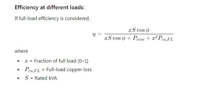
Condition for Maximum Efficiency
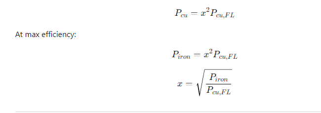
For a transformer, the efficiency is not constant but varies with the load. The maximum efficiency for a transformer is achieved at a specific load when the variable copper losses become equal to the constant core losses.
Condition for Maximum Efficiency:
Pcu = Pcore
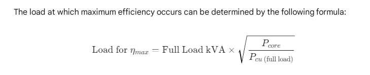
Load at Maximum Efficiency:
If ( Pcu,FL is copper loss at full load and efficiency is maximum at fractional load x , then:
All-Day Efficiency (ηall−day)
- Used for distribution transformers which operate 24 hours a day with varying loads.
- It considers the energy output and energy losses over 24 hours, not just instantaneous power.
For certain transformers, especially distribution transformers that are connected to the grid 24 hours a day but do not operate at full load continuously, the standard efficiency calculation may not be a true indicator of their performance. In such cases, all-day efficiency is a more relevant measure.
All-day efficiency, also known as energy efficiency, is the ratio of the total energy output in a 24-hour period to the total energy input over the same period, both measured in kilowatt-hours (kWh).
The formula for all-day efficiency is:
η all day = [Total Energy Input in 24 hours (kWh) / Total Energy Output in 24 hours (kWh)] ×100%

Since distribution transformers have their primary windings energized continuously, the core losses occur throughout the day, whereas the copper losses vary with the load fluctuations. Therefore, for a high all-day efficiency, it is crucial that the transformer has low core losses.
Key Points:
- Iron losses occur all the time, even at no-load.
- Copper losses depend on load current and vary during the day
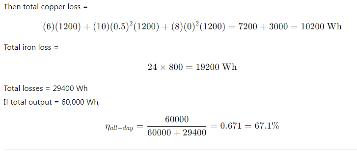
Example Calculation:
If a transformer operates at 6 hrs at full load, 10 hrs at half load, 8 hrs at no load and Iron loss = 800 W, Full-load copper loss = 1200 W
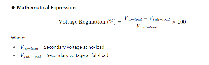
Transformer Voltage Regulation:
Definition:
The voltage regulation of a transformer is the change in secondary terminal voltage from no-load to full-load, expressed as a percentage of the full-load voltage, when the primary voltage remains constant.
Explanation:
- When the transformer is at no-load, only a small current flows to supply the core losses, so voltage drop is negligible.
- When load is applied, current increases, causing voltage drops across:
- The resistance (R) of the winding → ( I R ) drop
- The leakage reactance (X) of the winding → ( I X ) drop
- These drops cause the terminal voltage to fall under load.
Phasor Diagram Explanation (Simplified):
Depending on the power factor (pf) of the load:
- Lagging Power Factor (Inductive Load):
- Voltage drop is more because both (I R) and (I X) act in the same direction (partially additive).
- Regulation is positive.
- Unity Power Factor (Resistive Load):
- Voltage drop mainly due to (I R) only.
- Regulation is moderate.
- Leading Power Factor (Capacitive Load):
- (I X) drop acts in opposite direction to ( I R ).
- Regulation may become zero or negative.

Typical Values of Voltage Regulation:
| Transformer Type | Regulation at Full Load |
| Power Transformer | 1% to 2% |
| Distribution Transformer | 3% to 5% |
Factors Affecting Voltage Regulation
Several factors influence a transformer’s voltage regulation:
- Winding Resistance and Reactance: The internal impedance of the transformer, which is a combination of the winding’s resistance and leakage reactance, is the primary cause of voltage drop. As the load current increases, the voltage drop across this impedance also increases.
- Load Current: The magnitude of the current drawn by the load directly affects the voltage drop. Higher load currents lead to greater voltage drops and, consequently, poorer voltage regulation.
- Power Factor of the Load: The power factor of the load significantly impacts voltage regulation.
- Lagging Power Factor (Inductive Loads): This is the most common scenario. The voltage drop is more pronounced, leading to a positive and higher voltage regulation.
- Leading Power Factor (Capacitive Loads): With a leading power factor, the voltage drop can be partially or completely offset. In some cases, the full-load voltage can be higher than the no-load voltage, resulting in negative voltage regulation.
- Unity Power Factor (Resistive Loads): The voltage drop is primarily due to the winding resistance.
Why is Voltage Regulation Important?
Maintaining good voltage regulation is crucial for the proper functioning and longevity of electrical equipment for several reasons:
- Equipment Performance: Many electrical devices are designed to operate within a specific voltage range. Significant voltage variations can lead to malfunction, reduced efficiency, and a shorter lifespan. For instance, motors may overheat and lose torque with low voltage, while electronic devices can be damaged by high voltage.
- System Stability: In a power distribution system, consistent voltage levels are essential for overall stability. Poor voltage regulation in transformers can contribute to voltage instability and fluctuations throughout the grid.
- Power Quality: Good voltage regulation is a key aspect of power quality. It ensures that consumers receive a steady and reliable power supply, which is critical for sensitive electronic equipment and industrial processes.
Transformer MCQ Quiz Test