Speed Control of 3-Phase Induction Motor
The speed of a 3-phase induction motor is primarily determined by two factors:
- Synchronous Speed (Ns): The speed at which the magnetic field of the stator rotates. It depends on the frequency of the supply and the number of poles of the motor.
Ns=120×f /P
Where:
- Ns = synchronous speed (in RPM)
- f = frequency of the supply (in Hz)
- P = number of poles of the motor
- Slip (S): The difference between the synchronous speed and the actual speed of the rotor. The rotor always tries to catch up with the synchronous speed but never quite reaches it.
S=Ns−Nr / Ns
Where:
- Nr = rotor speed (in RPM)
- Ns = synchronous speed (in RPM)
The speed of an induction motor is slightly less than the synchronous speed, depending on the load. Slip increases with the load, causing the rotor to slow down and producing the necessary torque. However, for some applications, it’s essential to control or adjust the speed of the motor. There are several methods for controlling the speed of a 3-phase induction motor:
Methods of Speed Control of 3-Phase Induction Motor
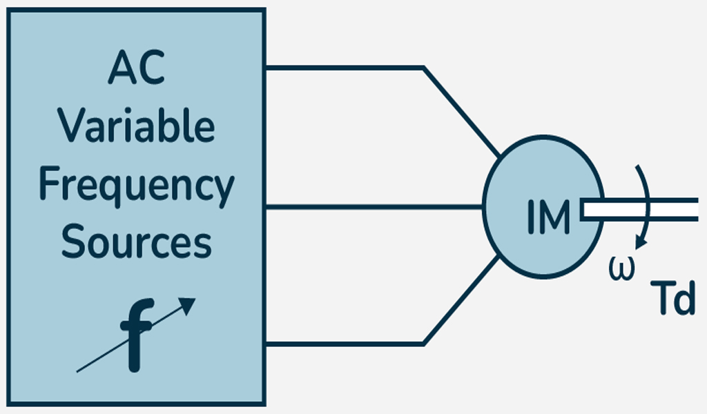
Varying the Supply Frequency (Variable Frequency Drive – VFD)
- The synchronous speed of an induction motor is directly proportional to the supply frequency. By varying the frequency of the AC supply, the synchronous speed of the motor changes, which in turn changes the motor’s speed. A Variable Frequency Drive (VFD) or Inverter is used to control the frequency and voltage applied to the motor. VFDs convert the fixed AC supply into a variable-frequency supply, allowing precise control over the motor speed.
Advantages:
- Precise control of speed over a wide range.
- Efficient in energy use, especially when loads vary.
- Smooth start and stop.
Disadvantages:
- Expensive setup, as VFDs can be costly.
- Requires periodic maintenance.
Changing the Number of Poles (Pole Changing Method)
- The synchronous speed of the motor is determined by the number of poles in the stator. By switching the stator windings to change the number of poles, the speed of the motor can be changed.In motors with pole-changing windings, two or more sets of windings are used. By switching between these windings, the number of poles is changed, which in turn changes the synchronous speed of the motor.
Speed Equation:
- For a 2-pole motor: Ns=120×f / 2
- For a 4-pole motor: Ns=120×f /4
Advantages:
- Simple method with minimal equipment.
- Provides step-wise speed variation.
Disadvantages:
- Limited to specific speeds (only step changes).
- Not ideal for continuous or fine control.
Varying the Voltage (Using Autotransformer or Series Resistance)
- Speed is related to the voltage applied to the motor. By reducing the voltage, the motor speed decreases. However, reducing the voltage also reduces the torque produced by the motor.
- Autotransformer Method: An autotransformer can be used to reduce the voltage supplied to the motor during starting. This reduces the starting current and limits the torque. After the motor reaches a certain speed, the autotransformer is switched out, and the full voltage is applied.
- Series Resistance Method: Adding resistors in series with the motor winding can reduce the voltage and, consequently, the motor speed. However, this method is inefficient due to energy losses in the resistors.
Advantages:
- Simple and inexpensive.
- Can be used for starting or for rough speed control.
Disadvantages:
- Reduces torque significantly.
- Increases power losses in the form of heat, especially with series resistance.
- Limited precision in speed control.
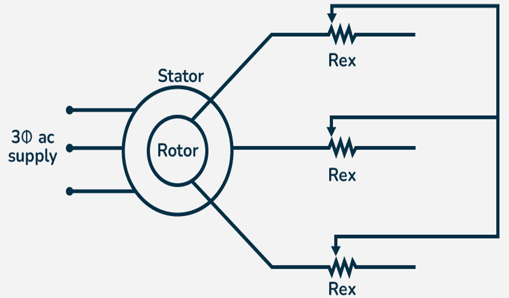
Rotor Resistance Control (Wound Rotor Motor)
- For wound rotor induction motors, the resistance of the rotor circuit can be increased to reduce the speed of the motor. By inserting external resistors in the rotor circuit, the overall resistance increases. This increases the slip, which leads to a reduction in the rotor speed. This method is usually used for speed control under load.
Advantages:
- Allows speed control without affecting the supply frequency.
- Can be used for specific load conditions where speed control is critical.
Disadvantages:
- External resistors generate heat, which leads to power loss.
- It is less efficient compared to frequency-based methods.
Pole Amplitude Modulation (PAM)
- Principle: This method is similar to pole-changing but is more advanced. By using a combination of pole-winding configurations and altering the magnetic field distribution, the motor speed can be continuously controlled.
- Working: Specially designed pole windings are used to achieve intermediate pole configurations. This provides a continuous range of speeds between the discrete speed steps offered by the basic pole-changing method.
Advantages:
- Provides continuous speed variation.
- More efficient than using series resistance for speed control.
Disadvantages:
- Complex design.
- Expensive.
Conclusion:
The most commonly used and effective method for controlling the speed of a 3-phase induction motor is the Variable Frequency Drive (VFD), which provides precise and energy-efficient control over the motor speed across a wide range. However, other methods like pole changing, voltage control, and rotor resistance control may be used depending on the application, cost considerations, and speed control requirements.
Mathematical Problems Solve
Question-1: A 3-phase induction motor has 4 poles and is supplied with a 50 Hz frequency. Calculate the synchronous speed.
Solution: Ns = 120×f / p, Ns= (120 * 50) / 4 = 1500 RPM
Question-2: An induction motor has a synchronous speed of 1800 RPM and a rotor speed of 1710 RPM. Calculate the slip.
Solution: S= (Ns – Nr / Ns)x100 = (1800 – 1710) / 1800 = 0.05 or 5%
Question-3: A motor with a synchronous speed of 1200 RPM has a slip of 0.04. What is the rotor speed?
Solution: S=Ns−Nr / Ns
=˃ 0.04 = (1200 – Nr) / 1200
=˃ 48 = 1200 – Nr
=˃ Nr = 1152 RPM
Question-4: If the frequency supplied to a 4 pole induction motor is changed from 50Hz to 60Hz, what will the change in synchronous speed be?
Solution:
- Ns1 = (120 * 50) / 4 = 1500 RPM
- Ns2 = (120 * 60) / 4 = 1800 RPM
- The increase in speed is 300RPM.
Question-5: A 2 pole induction motor, has a synchronous speed of 3000 rpm. If the rotor speed is 2850 rpm, what is the slip percentage?
Solution: s = ((3000-2850)/3000) * 100 = 5%
Question-6: If the number of poles of an induction motor is doubled, how will the synchronous speed change, assuming the frequency remains constant?
Solution: The synchronous speed will be halved. Since Ns = (120 * f) / P,
if P is doubled, Ns is divided by 2.
Problem-7:
A 3-phase induction motor operates at 50 Hz and 400 V. It has the following specifications:
- Synchronous speed (Nsync) at 50 Hz = 1500 RPM
- Number of poles (P) = 4
- Rated slip (s) = 2% (0.02)
If the motor is run using a variable frequency drive (VFD) at 40 Hz (without changing the supply voltage), find the following:
- The new synchronous speed at 40 Hz.
- The actual speed of the motor at 40 Hz with the given slip.
- The new voltage applied to the motor if the voltage-to-frequency ratio is maintained constant (i.e., the voltage is reduced according to the frequency).
Solution:
Part 1: Find the new synchronous speed at 40 Hz.
The synchronous speed Nsync of an induction motor is given by:
Nsync=120×f / P
Where:
- Nsync is the synchronous speed (in RPM),
- f is the frequency (in Hz),
- P is the number of poles.
At 40 Hz, we can find the new synchronous speed.
Nsync=(120×40) / 4
=1200 RPM
Thus, the new synchronous speed at 40 Hz is 1200 RPM.
Part 2: Find the actual speed of the motor at 40 Hz.
The actual speed Nof the motor can be calculated using the slip formula:
N=Nsync×(1−s)
At 40 Hz, with a slip of 2% (0.02):
N=1200×(1−0.02)=1200×0.98=1176 RPM
Thus, the actual speed of the motor at 40 Hz is 1176 RPM.
Part 3: Find the new voltage if the voltage-to-frequency ratio is maintained constant.
When using a variable frequency drive (VFD), the voltage-to-frequency ratio is maintained constant. This means that the voltage is directly proportional to the frequency. So, the ratio of the new voltage Vnew at 40 Hz to the original voltage V50Hz at 50 Hz is the same as the ratio of the new frequency fnew to the original frequency f:
Vnew / V50Hz =fnew / f
Therefore,
Vnew = V50Hz × fnew / f
Substituting the values:
Vnew = (400×40) /50 = 400×0.8 =320 V
Thus, the new voltage applied to the motor at 40 Hz is 320 V.
MCQ Quiz Test Three Phase Induction Motor:
Three Phase Induction Motor part-1
Three Phase Induction M 0otor part-2
Three Phase Induction Motor part-3
Three Phase Induction Motor part-4
MCQ Quiz Test Single Phase Induction Motor:
Single Phase Induction Motor part-1
Single Phase Induction Motor part-2
Single Phase Induction Motor part-3
Single Phase Induction Motor part-4
Related posts:
Torque In Three Phase Induction Motor
What is a 3-Phase Induction Motor and How Does It Work?
Losses In Induction Motor
Equivalent Circuit Of Induction Motor