Definition of Skin effect. Write factors affecting skin effect in transmission line
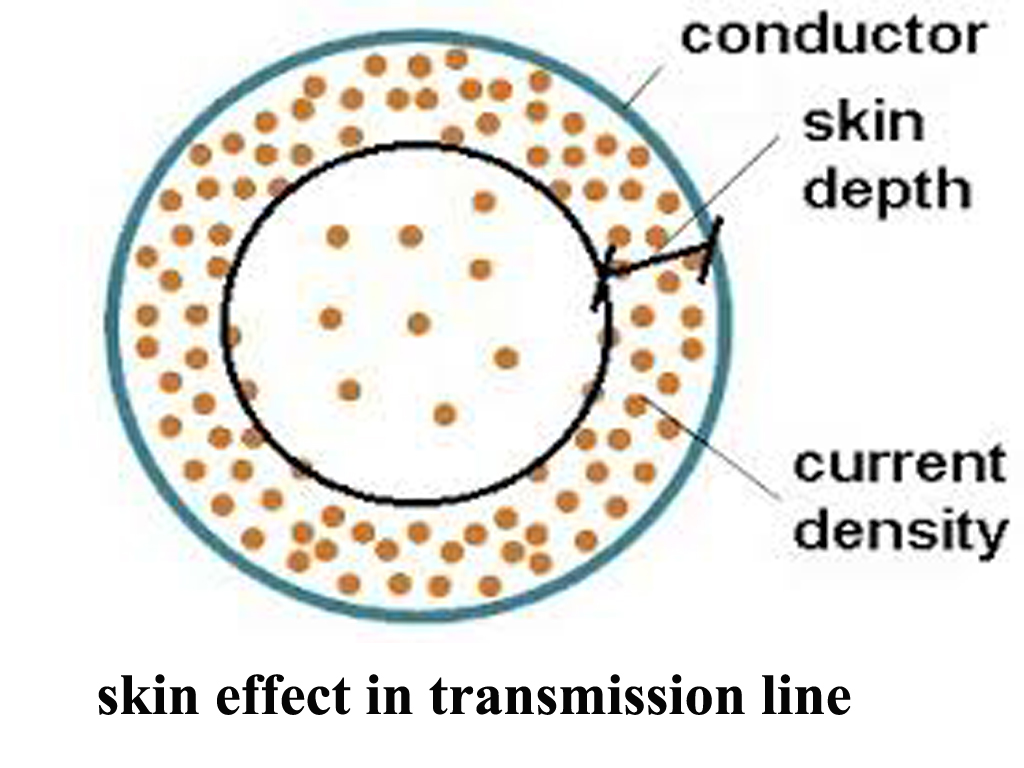
Answer: The skin effect is a phenomenon where alternating current (AC) tends to flow primarily near the surface of a conductor, concentrate towards the “skin” or outer surface of a conductor, rather than being evenly distributed throughout its cross-section. This results in a higher current density near the surface and a lower current density in the center.
Factors Affecting Skin Effect in Transmission Lines:
Frequency:
- The skin effect increases significantly with higher frequencies. As the frequency of the AC increases, the current is pushed further towards the conductor’s surface.
Conductor Material:
- The conductivity and permeability of the conductor material play a role. Materials with higher permeability (like ferromagnetic materials) exhibit a more pronounced skin effect.
Conductor Diameter:
- Larger diameter conductors experience a greater skin effect. The larger the conductor, the more pronounced the concentration of current at the surface.
Conductor Shape:
- The shape of the conductor also influences the skin effect. Solid conductors have a greater skin effect compared to stranded conductors. Stranded conductors, like ACSR (Aluminum Conductor Steel Reinforced), are designed to mitigate the skin effect.
Temperature:
- Temperature can slightly influence the skin effect, as it affects the conductivity of the material.
Why Skin effect occurs?
Magnetic Field and Eddy Currents:
- When an alternating current flows through a conductor, it creates a changing magnetic field around that conductor. This changing magnetic field induces eddy currents within the conductor itself. These eddy currents circulate within the conductor, and their direction opposes the change in the original magnetic field (this is a manifestation of Lenz’s Law).
Electromagnetic Induction and Changing Magnetic Field:
- When an AC flows through a conductor, it generates a changing magnetic field around the conductor. According to Faraday’s Law of Induction, a time-varying magnetic field induces an electric field in the conductor.This induced electric field opposes the flow of current deeper inside the conductor, effectively limiting the amount of current that can flow through the interior of the conductor.
Frequency Dependence:
- The skin effect becomes more pronounced as the frequency of the AC increases. At higher frequencies, the electromagnetic waves generated by the current are more likely to induce opposing currents deeper into the conductor, resulting in more current being confined to the outer regions of the conductor.
Formula for Skin Depth:
The skin depth (δ) can be approximated using the following formula:
δ= √(2ρ/μω)
Where:
- ρ = resistivity of the material,
- μ= permeability of the material,
- ω= angular frequency of the AC current (ω=2πf, where f is the frequency of the AC).
2. What is Ferranti effect?
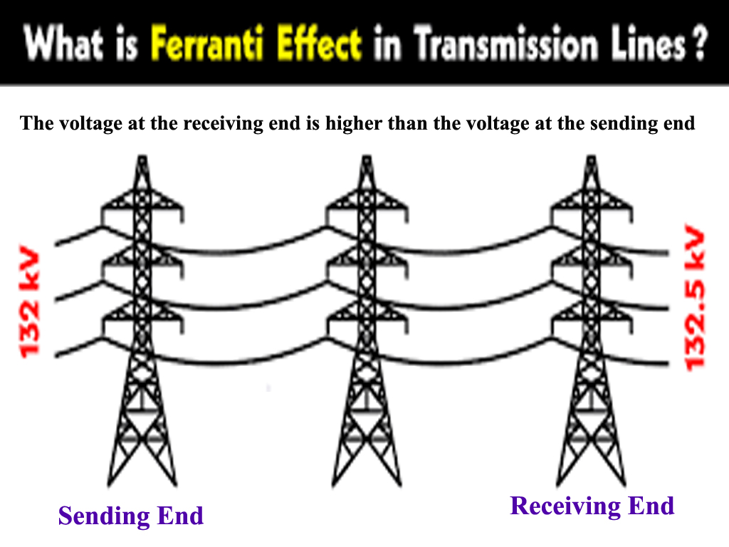
The Ferranti effect is a phenomenon in electrical power transmission where the voltage at the receiving end of a long AC transmission line is higher than the voltage at the sending end, especially under light load or no-load conditions. This effect typically occurs in high-voltage, long-distance transmission lines, underground cables that operate at or near the resonance frequency of the system.
Why Ferranti Effect Occurs:
The Ferranti effect arises due to the following reasons:
- Capacitance of the Transmission Line: Long transmission lines have a significant amount of capacitance, which causes the voltage at the receiving end to increase. In long transmission lines, the line’s capacitance and inductance cause a phase shift in the voltage, which, under light load conditions, leads to a rise in voltage.
- Under Light Load or No Load Conditions: Under conditions of light load or no load, the line’s reactive power (mainly capacitive) is not fully absorbed by the load. The energy stored in the line’s capacitance gets released back into the line, leading to an increase in the receiving end voltage.
- Inductive and Capacitive Reactance Interaction: A transmission line is a combination of inductive and capacitive reactance. The inductive reactance tends to drop the voltage at the receiving end, while the capacitive reactance tends to raise it. Under normal or light loading conditions, the capacitive effect can dominate, causing the receiving end voltage to rise above the sending end voltage.
How to Reduce the Ferranti Effect:
- Series Reactance Compensation: Introducing series inductance or series capacitors along the transmission line can help counteract the capacitive effect. By adding series reactors or inductors, you can reduce the voltage rise at the receiving end. This approach effectively balances the capacitive and inductive effects on the line.
- Shunt Reactors: These are inductive devices connected in parallel with the transmission line. Installing shunt reactors (or inductive reactors) at the receiving end of the transmission line can help absorb the excess reactive power that is causing the voltage to rise. The shunt reactors counteract the effects of line capacitance, reducing the Ferranti effect.
- Voltage Regulators: Voltage regulators can be installed to maintain a constant voltage at the receiving end of the transmission line, compensating for any fluctuation caused by the Ferranti effect.
- Transmission Line Shortening: Reducing the length of the transmission line, if possible, can minimize the effect because shorter lines have less capacitance and therefore less potential for a voltage rise.
- Using Higher Load Conditions: Ensuring that the transmission line is loaded adequately can help reduce the Ferranti effect. When the line is carrying higher load, the capacitive reactance effect is less likely to dominate, and the voltage difference between the sending and receiving ends is reduced.
3. What is the Proximity Effect?
The proximity effect refers to the phenomenon where the current distribution in a conductor is altered due to the presence of nearby conductors carrying current. This effect is particularly noticeable in AC (alternating current) circuits, where the alternating magnetic fields generated by the current in one conductor induce circulating currents in nearby conductors. These circulating currents cause the current in the conductor to be concentrated closer to the surface facing the other conductor, increasing the effective resistance and power loss in the conductor.
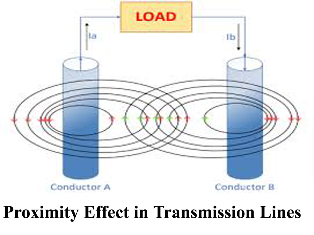
In simpler terms, when two or more conductors are placed near each other and carry alternating currents, the magnetic field generated by one conductor induces current in the adjacent conductor, causing a distortion in the current flow. The result is that the current is concentrated on the outer edges of the conductors, especially near the area facing the other conductor.
Why Does the Proximity Effect Occur?
The proximity effect occurs because of the interaction between the magnetic fields of conductors carrying alternating currents. The key factors contributing to this effect are:
- Magnetic Field Interaction: When an alternating current flows through a conductor, it creates a time-varying magnetic field around the conductor. If another conductor is placed nearby, this time-varying magnetic field induces eddy currents in the second conductor, which affects the current distribution in that conductor.
- Skin Effect and Proximity Effect Interaction: The skin effect refers to the tendency of alternating current to flow mainly on the surface of a conductor. The proximity effect is a similar phenomenon, but it occurs due to the influence of nearby conductors. Both effects lead to a non-uniform current distribution, but the proximity effect is more pronounced when conductors are placed close to each other.
- Reduced Effective Cross-Section: Due to the altered current distribution (with current concentrating at the outer edges of the conductor), the effective cross-sectional area available for current flow is reduced. This leads to an increase in the effective resistance of the conductor, resulting in higher power loss.
How to Reduce the Proximity Effect:
Several strategies can minimize the proximity effect:
- Increase Conductor Spacing: Increasing the distance between conductors reduces the strength of the magnetic fields interacting with each other, thus lessening the effect.
- Use of Litz Wire: Litz wire is a type of wire designed to reduce the effects of both the proximity and skin effects. It consists of many thin, insulated wires twisted together. The individual wires in Litz wire can carry current through different paths, which helps reduce the overall resistance caused by the proximity effect. This is especially useful in high-frequency applications.
- Reduce Frequency: The proximity effect is more pronounced at higher frequencies. Therefore, reducing the frequency of the AC current can help mitigate the effect.
- Twisted Pairs of Conductors: In some cases, using twisted pairs of conductors helps distribute the proximity effect more evenly. The twisting of the wires ensures that any one part of the conductor is not consistently exposed to the same magnetic field from nearby conductors.
- Conductor Arrangement: Careful arrangement of conductors can minimize the impact of their magnetic fields. For example, in transformers, interleaving the windings can help.
- Optimizing Conductor Shape: In some applications, optimizing the shape of the conductors can reduce the proximity effect.
- Use of Insulation and Shielding: Adding insulation between conductors or placing conductors in shielded enclosures can help minimize the effects of proximity. This approach prevents direct magnetic field interaction between conductors, reducing the induced currents and the proximity effect.
- Using Larger Conductors: Increasing the size (diameter) of conductors helps reduce the relative importance of the proximity effect. A larger conductor has more surface area and can allow current to spread out more evenly, reducing the concentration of current near the surface.