Over Current Relay (50/51) Definition:
An Overcurrent Relay (OCR) is a protective relay that operates when the current exceeds a predetermined value (pickup current). It helps detect and isolate faults such as short circuits or overloads in the power system.
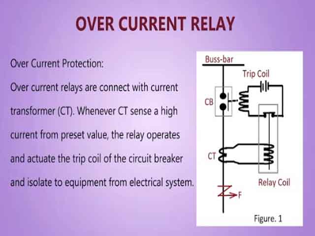
Why Over current Protection?
Excessive current, whether due to a phase-to-phase short circuit, a phase-to-ground fault, or an extreme overload, generates immense heat proportional to the square of the current (P=I2R). This heat can quickly melt conductors, damage insulation, and cause catastrophic failure of transformers, generators, and cables. The 50/51 relay works by constantly monitoring the system current (via Current Transformers or CTs) and comparing it to a set pickup value. When the current exceeds this limit, the relay initiates a trip signal to the associated circuit breaker.
ANSI codes:
50 → Instantaneous Over current Relay
51 → Time-Over current Relay
50G → Ground Fault Over current Relay
50N → Neutral Instantaneous Over current Relay
51N → Neutral Inverse Time Over current Relay
Functions:
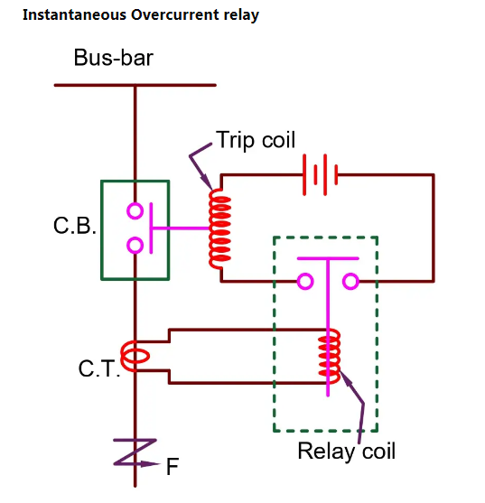
50: The Instantaneous Over current Relay Element
A. Principle of Operation
The Instantaneous Over current (IOC) element, designated as ANSI 50, is designed for speed. As its name suggests, it operates with no intentional time delay when the current exceeds its set threshold. Its primary role is to provide fast fault clearance for high-magnitude faults, typically those very close to the power source where the fault current is maximal.
In modern numerical relays, the instantaneous operation time is often less than 50 milliseconds (or 3 cycles on a 60 Hz system), ensuring damage is minimized for severe faults.
B. Key Setting: Pickup Current (I50P)
The only major setting for the 50 element is the Pickup Current (I50P), which is the minimum current that must flow through the relay for it to operate.
- Setting Philosophy: I50P is set above the maximum expected transient inrush current (like transformer magnetizing inrush) and above the maximum fault current that a downstream protective device should clear. This is crucial for discrimination—it ensures the 50 element only trips for a fault within its protected zone and acts as a backup for a nearby, downstream instantaneous element that should have cleared the fault already.
C. Application
- Primary Protection: For high-speed clearance of close-in, high-current faults.
- Backup Protection: To act as a fast backup for the time-delayed (51) element closest to the source, or for downstream instantaneous elements.
- Earth Fault (50N/G): An instantaneous earth fault element (often labelled 50N for neutral or 50G for ground) is highly sensitive and set to rapidly clear ground faults, which often have low current magnitudes but are very damaging.
- Characteristics:
- No time delay.
- Trip time ≈ 0 seconds after pickup.
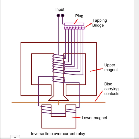
51: The Inverse Time Over current Relay Element
A. Principle of Operation
The Time Over current (TOC) or Inverse Definite Minimum Time (IDMT) element, designated as ANSI 51, is the workhorse of coordination. It operates with a time delay that is inversely proportional to the magnitude of the fault current.
- Inverse Characteristic: A very high fault current causes a fast trip, while a current just above the pickup value results in a slow, deliberate This characteristic is ideal because fault severity (damage potential) is proportional to current magnitude and duration.
B. Key Settings
The 51 element requires two primary settings to define its time-current characteristic curve:
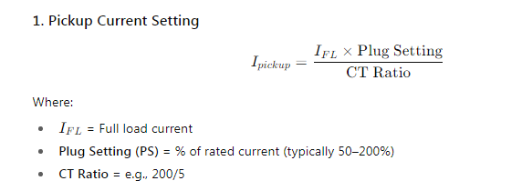
1. Pickup Current (I51P) or Plug Setting (PS)
This is the minimum current required to start the timing function of the relay. It’s typically set above the maximum continuous load current and below the minimum fault current in the protected zone. The Pickup Current is often expressed as a multiple of the CT Secondary Rating (e.g., 5A or 1A).
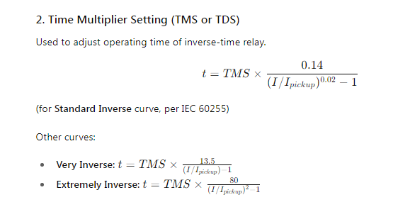
2. Time Multiplier Setting (TMS) or Time Dial Setting (TD)
This setting shifts the entire time-current curve up or down on a log-log plot.
- A lower TMS (e.g., 0.1) results in a faster trip time for any given current multiple.
- A higher TMS (e.g., 1.0) results in a slower trip time.
The operating time (T) for any given current multiple (M) is calculated using a standard formula:

Where A, B, and P are constants specific to the chosen curve type, and M is the Multiple of Pickup Current (IFault/I51P).
C. Time-Current Characteristic Curves
The “shape” of the inverse curve is defined by the standards (IEC or IEEE/ANSI) and is selected based on the application and the upstream/downstream protective devices. The most common IEC/IEEE curves are:
| Curve Type | Characteristic | Primary Application |
| Normal (Standard) Inverse | Moderate slope. | General purpose, excellent for coordination. |
| Very Inverse | Steeper slope. | Faster at high current, better for coordinating with fuses and downstream devices. |
| Extremely Inverse | Steepest slope. | High sensitivity to high currents, often used for protection against thermal damage (e.g., generator or transformer windings, coordinating with fuses). |
| Long-Time Inverse | Very slow operation. | Used primarily for thermal overload protection where an overcurrent is tolerated for a long period. |
- Characteristics:
- Trip time decreases as fault current increases.
Common curves: Inverse, Very Inverse, Extremely Inverse.
3. 50G (Ground Fault Over current):
- Focused on ground fault detection, this relay isolates ground faults quickly, ensuring the safety of grounded systems—critical in environments with solidor low-resistance grounding.
4. 50N (Neutral Instantaneous Over current Relay):
- Provides instantaneous or very rapid tripping when the neutral/earth fault current exceeds a preset pickup value (Ipickup). It operates with no intentional time delay (typically less than a few cycles, e.g., <50 milliseconds). It is used for high-magnitude earth faults, such as those caused by a solid short-circuit, which require immediate isolation to minimize damage to equipment. It acts as a primary protection for severe earth faults or as a high-set instantaneous element for a 51N
51N (Neutral Inverse Time Over Current Relay):
- It Provides tripping when the neutral/earth fault current exceeds a preset pickup value (Ipickup) with a time delay that is inversely proportional to the current magnitude. This is also known as IDMT (Inverse Definite Minimum Time) The higher the fault current, the shorter the operating time. Conversely, for a lower fault current (but still above Ipickup), the relay will take longer to trip. The exact time-current characteristic is determined by selecting a specific curve (e.g., standard inverse, very inverse, extremely inverse) and setting a Time Multiplier Setting (TMS) or Time Dial (TD).
It is the most common form of earth fault protection, essential for achieving coordination or selectivity with other protective devices (like other relays, fuses, or circuit breaker trip units) further downstream. This ensures that only the protective device closest to the fault operates, thereby minimizing the extent of the outage.
Combined & Related Functions of Over Current Relay:
| Function | Description |
| 50 | Instantaneous over current Relay |
| 51 | Time-over current Relay |
| 50N / 51N | Neutral (or ground) over current Relay |
| 50G / 51G | Neutral (or ground) over current Relay |
| 50BF | Breaker failure protection |
| | 51V | Voltage-restrained over current Relay | |
| 51C | Current-controlled time-over current Relay |
Note: In many modern digital relays, 50 and 51 functions are combined, one relay performs instantaneous and time-delayed overcurrent protection simultaneously.
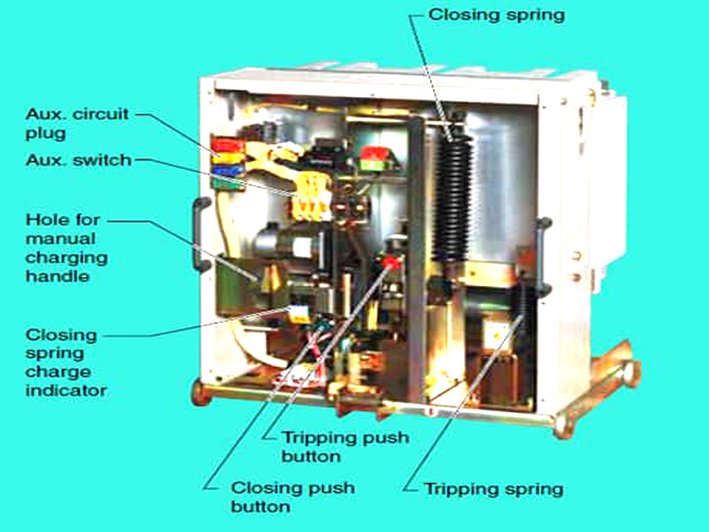
Working Principle
The Over Current Relay works on the electromagnetic induction principle (in electromechanical types) or signal processing (in digital relays). Over current relays, historically electromechanical or modern microprocessor-based, work by continuously monitoring the line current via a Current Transformer (CT). When the measured current exceeds a set “pickup” value:
- Sensing: Current Transformer (CT) measures line current. The CT steps down the high primary current to a low, measurable secondary current (e.g., 5 A or 1 A nominal).
- Comparison: The relay compares this secondary current to its set pickup current.
- Operation (Trip): If the current exceeds the pickup, the relay initiates a trip signal to the circuit breaker after a time delay determined by its specific function (50 or 51). The circuit breaker then opens its contacts to isolate the faulty section.
Protection Functions of Over Current Relay/Earth Fault Relays
The primary protection provided by 50/51 and 50N/51N relays includes:
- Short Circuit Protection (Faults): Clearing high-magnitude phase-to-phase, phase-to-ground, or three-phase faults.
- Overload Protection (Sustained High Current): Protecting equipment (like cables, transformers, and motors) from sustained over currents that cause overheating, mainly handled by the inverse time function (51).
- Earth Fault/Ground Fault Protection: Clearing faults to ground/earth, often via dedicated neutral current settings (50N/51N) which are typically more sensitive than phase settings.
- Phase Fault Protection (50/51): – protects against overcurrent between phases.
- Backup Protection: – serves as backup if primary protection fails.
- Feeder, Transformer, and Generator Protection: provides overload and fault isolation.\
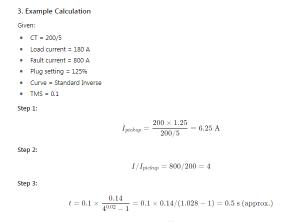
Relay Setting Calculations:
Evolution and Modern Implementations
50/51 relays were electromechanical (induction disc and solenoid plungers).
- Electromechanical Relays: Function 51 utilized a rotating aluminum disc (induction disc) whose rotation speed was proportional to the current, and a time dial set the contact travel distance (TMS). Function 50 used a magnetic coil/plunger. While robust, they lacked flexibility and had fixed curve shapes.
- Digital/Numerical Relays: Modern microprocessor-based relays combine the 50 and 51 functions (and many others, like 50N/51N) into a single, highly flexible unit. They allow for multiple, selectable curve types, precise digital settings for I50P, I51P, and TMS, and offer advanced features like event logging, oscillography, and communications. This has vastly improved coordination accuracy and system diagnostics.