What is an Operational Amplifier (Op-Amp) ?
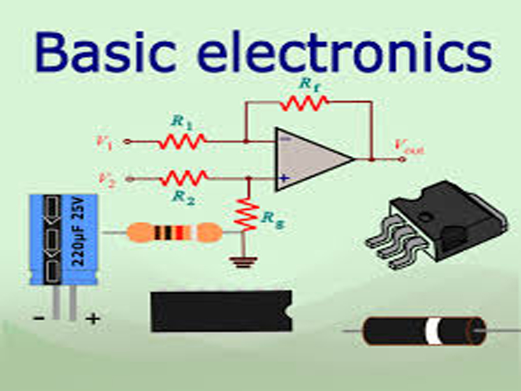
An operational amplifier (often shortened to op-amp) is a DC-coupled high-gain electronic voltage amplifier with a differential input and a single-ended output. It is one of the most versatile and fundamental building blocks in analog electronic circuits.
The name “operational amplifier” comes from its original use in analog computers, where it was employed to perform mathematical operations such as addition, subtraction, integration and differentiation.
An ideal op-amp possesses several key characteristics, which practical op-amps aim to approximate:
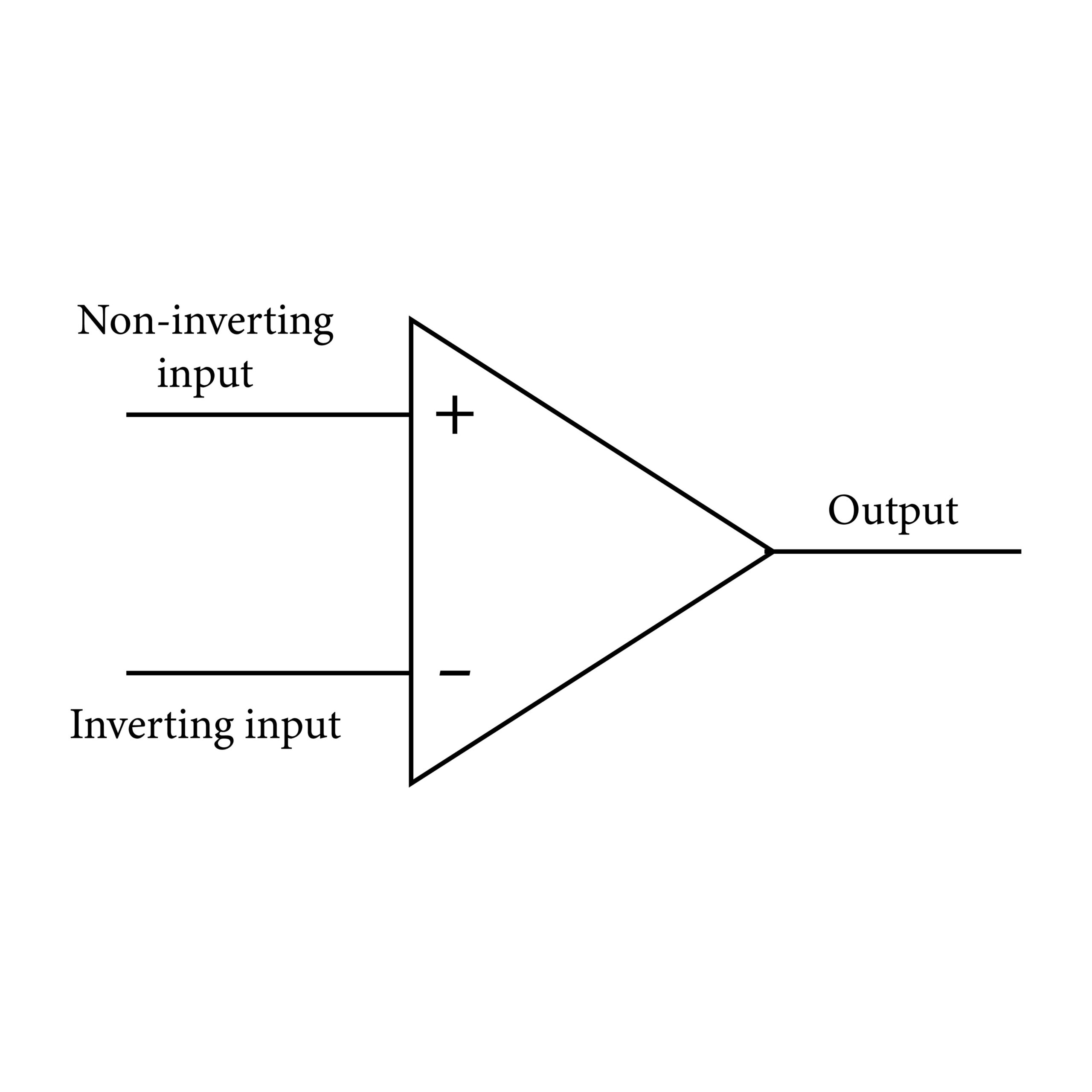
- Differential Input: It has two input terminals:
- Non-inverting input (+): The output signal is in phase with the signal applied here.
- Inverting input (-): The output signal is 180° out of phase with the signal applied here.
- High Open-Loop Gain (A): The gain without any feedback is extremely high (ideally infinite, but typically 10,000 to 200,000 in practice).
- High Input Impedance (Zin): Ideally infinite, meaning virtually no current flows into the input terminals.
- Low Output Impedance (Zout): Ideally zero, allowing it to drive a significant load.
- Operation: The op-amp amplifies the difference between the voltages at the two input terminals, Vout = A (V+ – V–).
Types of Operational Amplifier (Op-Amp) Configurations
Op-amps are rarely used in their “open-loop” (no feedback) form, as the high gain makes the output saturate easily, making them primarily useful as a comparator (for comparing two voltages).
By adding external components like resistors and capacitors to create a feedback loop, the op-amp’s function, gain, and performance can be precisely controlled. The different ways these components are connected create different circuit types or configurations:
Basic of an Operational Amplifier (Op-Amp) Configurations
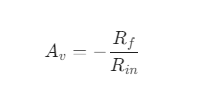
- Inverting Amplifier: The input signal is applied to the inverting terminal, and the non-inverting terminal is grounded. The output is amplified and inverted (180° phase shift). The voltage gain Av is determined by the feedback resistor (Rf) and input resistor (Rin):
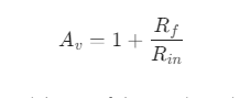
- Non-Inverting Amplifier: The input signal is applied to the non-inverting terminal. The output is amplified and in phase with the input. The voltage gain Av is:
- Voltage Follower (Buffer): A special case of the non-inverting amplifier where the output is directly connected to the inverting input (100% negative feedback). The gain is unity (Av = 1). It’s used for impedance matching and buffering signals.
Functional Configurations
- Summing Amplifier (Adder): Combines and scales multiple input signals into a single output.
- Differential Amplifier (Subtractor): Amplifies the difference between two input signals.
- Integrator: Produces an output voltage proportional to the time integral of the input voltage. (Uses a capacitor in the feedback path).
- Differentiator: Produces an output voltage proportional to the time derivative of the input voltage. (Uses a capacitor at the input).
Classification by Internal Structure/Features
Op-amps can also be classified based on their internal design or specialized features:
- Voltage Feedback Op-Amps: The most common type; they amplify the voltage difference.
- Current Feedback Op-Amps: Offer higher bandwidth and slew rates, often used in high-speed applications.
- Rail-to-Rail Op-Amps: Designed so their input and output voltages can operate close to the power supply rails (the maximum positive and minimum negative voltage supplies).
- Low-Power Op-Amps: Optimized for minimal current consumption, ideal for battery-powered devices.
- Precision/Zero-Drift Op-Amps: Designed to minimize voltage offset and drift over temperature, used for high-accuracy measurements.
What is an Ideal Operational Amplifier (Op-Amp)?
An ideal operational amplifier (Op-Amp) is a theoretical model used in circuit analysis to simplify calculations and understand the fundamental behavior of op-amp circuits. It represents a perfect, high-performance device with characteristics that real-world op-amps strive to emulate.
While no real op-amp can perfectly match the ideal model, the ideal characteristics are often very close to those of practical, high-quality op-amps, especially when used with negative feedback.
Characteristics of an Ideal Op-Amp
The ideal op-amp is defined by a set of characteristics that make its analysis straightforward. These properties are key to the function and versatility of op-amps in a wide range of electronic circuits:
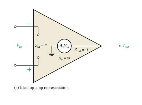
- Infinite Open-Loop Voltage Gain (AVOL = ∞) The gain of the amplifier without any feedback is infinitely large.
- Infinite Input Impedance (Zin = ∞): No current flows into the input terminals (the op-amp acts as a perfect voltmeter).
- Zero Output Impedance (Zout = 0): The op-amp can drive any load without affecting its output voltage (the op-amp acts as a perfect voltage source).
- Infinite Bandwidth (BW = ∞): The amplifier can amplify signals of any frequency, from DC up to infinity, without the gain dropping.
- Zero Input Offset Voltage (Vos = 0 ): When the voltages at both input terminals are equal, the output voltage is exactly zero.
- Infinite Slew Rate (SR = ∞): The output voltage can change instantaneously, meaning the op-amp can perfectly track high-speed signals.
- Infinite Common-Mode Rejection Ratio (CMRR = ∞): The op-amp completely rejects any signal that is common to both input terminals (common-mode noise).
What is practical Operational Amplifier (Op-Amp)?
A practical operational amplifier (also called a non-ideal op-amp) is an actual, physical integrated circuit (IC) that is manufactured for use in real electronic circuits.
Unlike the theoretical “ideal” model, a practical op-amp has finite values for its characteristics and exhibits several imperfections due to the limitations of semiconductor manufacturing, materials and physics.
In most common applications using negative feedback, a practical op-amp performs closely enough to the ideal model that the ideal equations can be used for initial design. However, for high-precision, high-speed, or low-voltage circuits, the practical limitations must be carefully considered.
Characteristics of an practical Op-Amp:
- Finite Open-Loop Voltage Gain (AVOL): The gain is not infinite but very large (e.g. 20,000 to 200,000).
- Finite Input Impedance (Zin): The input impedance is not infinite but very high (e.g. MΩ to TΩ), causing a small amount of current to flow into the inputs.
- Non-Zero Output Impedance (Zout): The output impedance is not zero but low (e.g. 10Ω to 100Ω), limiting the maximum current the op-amp can deliver to a load.
- Finite Bandwidth (BW): The gain of the op-amp decreases as the frequency of the input signal increases.
- Non-Zero Input Offset Voltage (VOS): A small voltage (typically mV or less) exists between the input terminals when the output is zero. This must be compensated for in precision circuits.
- Non-Zero Input Bias Current (IB): Small DC currents flow into the two input terminals to properly bias the internal transistors, causing errors in circuits with high input resistance.
- Finite Slew Rate (SR): The output voltage can only change at a maximum finite speed (e.g. 5 V/µs). This limits the op-amp’s ability to handle fast-changing, large-amplitude signals.
- Finite Common-Mode Rejection Ratio (CMRR): The op-amp does not perfectly reject common-mode signals (noise applied to both inputs), allowing a small amount of common-mode voltage to appear at the output.
- Limited Power Supply Range: The output voltage can never exceed the positive power supply (+VCC) or drop below the negative power supply (-VEE).
Input signal moods of op amp:
The operational amplifier (op-amp) is fundamentally a differential amplifier, meaning it is designed to respond to the difference between the two input signals. The signals applied to the two input terminals the non-inverting input (V+) and the inverting input (V–) can be decomposed into two fundamental signal modes: the Differential Mode and the Common Mode.
1. Differential Mode Input (Vd)
The Differential Mode Input is the signal that the op-amp is designed to amplify. It is the difference between the two input voltages.
Calculation and Gain
The differential voltage (Vd is calculated as: Vd = V+ – V–
In the ideal case, the output voltage (Vout) of the op-amp is directly proportional to the differential mode input voltage, amplified by the Differential Gain (Ad):
Vout ≈ Vd . Ad
Characteristics
- Signals: The two signals are opposite in phase (180° out of phase) with respect to ground. For a pure differential signal, V+ = Vin/2 and V– = – Vin/2
- Purpose: This is the useful signal you want to amplify. A good op-amp has an extremely high differential gain (Ad), which is why the op-amp’s open-loop gain is so large.
2. Common Mode Input (Vcm)
The Common Mode Input is the signal that appears identically on both input terminals. This is often an unwanted signal, like noise or interference, picked up equally by both input wires.
Calculation and Rejection
The common mode voltage (10cm) is calculated as the average of the two input voltages:
Vcm = (V+ + V– )/2
The op-amp amplifies the common mode voltage by a very small factor called the Common Mode Gain (Acm). Ideally, Acm should be zero. The output contribution from this signal is:
Vout (common) = Vcm . Acm
Characteristics:
- Signals: The two signals are in phase and of equal magnitude with respect to ground.
- Purpose: The op-amp is designed to reject or ignore the common mode signal. The ability to reject it is measured by the Common Mode Rejection Ratio (CMRR), where:
CMRR = Ad / Acm
A high CMRR is a desirable characteristic for an op-amp, as it allows it to effectively cancel noise.
Total Output Voltage
In a real-world scenario, the output voltage is the sum of the amplified differential signal and the amplified common mode signal:
Vout = (Ad .Vd) + (Acm.Vcm)
Because Ad is typically huge and Acm is ideally very small, the output is overwhelmingly dominated by the intended differential signal, achieving effective noise rejection.
Key Parameters of Operational Amplifiers
The performance of any Operational Amplifier (Op-Amp), whether ideal or practical, is defined by a specific set of parameters. These parameters are categorized based on whether they relate to the AC (frequency-dependent) or DC (static, low-frequency) behavior of the device.
I. DC (Static) Parameters
These parameters describe the op-amp’s performance at zero or very low frequencies, focusing on precision and bias conditions.
- Input Offset Voltage (VOS): The voltage that must be applied between the two input terminals to make the output voltage exactly zero. Ideally VOS = 0
Typical Real Value: A few microvolts (μV) to a few millivolts (mV).
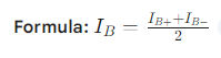
- Input Bias Current (IB): The average of the DC currents flowing into the two input terminals. Ideally IB = 0
Ideal Value: Zero (0 A).
Typical Real Value: Picoamperes (pA) for FET input types, to nanoamperes (nA) or microamperes (μA) for Bipolar Junction Transistor (BJT) input types.
- Input Offset Current (IOS): The difference between the two input bias currents. Ideally IOS = 0. It is a measure of the mismatch between the input terminals.
- Formula: IOS = IB+ – IB-
- Ideal Value: Zero (0 A).
- Typical Real Value: Much smaller than the input bias current.
- Input Impedance (ZIN):
- The resistance seen between the two input terminals (differential) or from each input to ground (common-mode).
- Ideal Value: Infinite (∞). This ensures the op-amp draws no current from the source.
- Typical Real Value: Mega ohms (MΩ) to Tera ohms (TΩ).
- Output Impedance (ZOUT):
- The resistance seen looking back into the output terminal.
- Ideal Value: Zero (0 Ω). This allows the op-amp to drive any load without a voltage drop.
- Typical Real Value: Low, typically tens to hundreds of ohms (Ω).
- Open-Loop Voltage Gain (AOL or Av):
- The ratio of the output voltage to the differential input voltage without any external feedback.
- Ideal Value: Infinite (∞)
- Typical Real Value: Very high, often 105 to 106 (100 dB to 120 dB).
- Common-Mode Rejection Ratio (CMRR): A measure of the op-amp’s ability to reject a voltage signal that appears identically at both inputs (common-mode voltage). Ideally CMRR = ∞
Typical Real Value: High, typically 70 dB to 120 dB.
AC Parameters
AC parameters describe the op-amp’s behavior with changing signals and frequency response.
- Slew Rate (SR):
- The maximum rate of change of the output voltage per unit of time. It limits how fast the output can respond to a large, rapid change in the input voltage.
- Unit: Volts per microsecond (V/μS).
- Ideal Value: Infinite (∞).
- Typical Real Value: Ranges from 5 V/μS (general purpose) to hundreds or thousands of V/μS (high-speed op-amps).
- Bandwidth (BW) / Gain-Bandwidth Product (GBWP):
- Bandwidth (BW): The range of frequencies over which the open-loop gain is above 707 AOL (DC) (the -3dB point).
- Gain-Bandwidth Product (GBWP or fT): The frequency at which the open-loop voltage gain drops to unity (1 or 0 dB). For a stable op-amp with one pole, the GBWP is nearly constant.
- Ideal Value: Infinite (∞).
- Typical Real Value: 1 MHz (general purpose) to over 1 GHz (high-speed).
- Power Supply Rejection Ratio (PSRR) / Supply Voltage Rejection Ratio (SVRR):
- A measure of the op-amp’s ability to maintain a constant output voltage despite variations in the power supply voltage.
- Unit: Microvolts per Volt (μV/V) or Decibels (dB).
- Ideal Value: Infinite (∞).
- Typical Real Value: High, typically 80dB to 120dB.