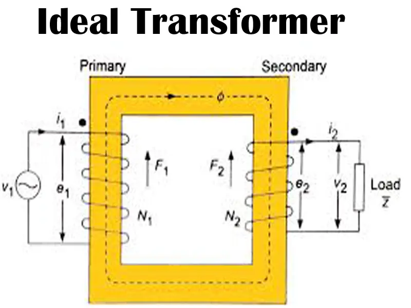
Ideal transformer:
An ideal transformer is a electrical static device that operates No losses (no copper loss, core loss, or leakage flux) and 100% efficiency. It is a fixed device that transform electrical energy from one circuit to another circuit while maintain fixed frequency. Also increasing or decreasing the current or voltage level.
Working Principle of an Ideal Transformer:
The working principle of an ideal transformer is based on Faraday’s Law of Electromagnetic Induction and mutual induction:
- Applied AC Voltage (Primary Side): When an alternating voltage (V1) is applied to the primary winding, it causes an alternating current (I1) to flow through it.
- Magnetic Flux Generation: This alternating current produces a time-varying magnetic flux (Φm) in the transformer’s core. In an ideal transformer, the core has infinite permeability, so a negligible magnetizing current is needed to establish this flux.
- Perfect Flux Linkage: Due to the ideal nature, all the magnetic flux (Φm) generated by the primary winding is perfectly confined to the core and links with every turn of both the primary and secondary windings. There is no leakage flux.
- Induced EMF (Primary Side): As per Faraday’s Law, this changing magnetic flux induces an electromotive force (EMF) E1 in the primary winding itself. By Lenz’s Law, E1 is equal in magnitude and opposite in phase to the applied voltage V1.
- Induced EMF (Secondary Side): The same changing magnetic flux also links with the secondary winding, inducing an EMF E2 in it. This is due to mutual induction. The magnitude of E2 is proportional to the number of turns in the secondary winding.
- Load Connection (Secondary Side): If a load is connected to the secondary winding, the induced EMF E2drives a current I2through the load.
- Power Conservation: In an ideal transformer, there are no losses (no copper losses, no core losses). Therefore, the instantaneous power input to the primary winding is equal to the instantaneous power output from the secondary winding: V2V1=N2N1
- This also means the apparent power (VA) is conserved.
- Voltage and Current Ratios: The ratio of voltages is directly proportional to the turns ratio, and the ratio of currents is inversely proportional to the turns ratio:
- V2V1=N2N1
- I1I2 =N2N1
🔹 EMF Equation
Let:
- V1 = primary voltage
- V2 = secondary voltage
- N1 = number of turns in the primary
- N2 = number of turns in the secondary
➤ Turns Ratio:
V2 / V1=N2 / N1
Also, in an ideal transformer:
- Power input = Power output
V1I1=V2I2 ⇒ I2 / I1= N1 / N2
Ideal transformer properties:
- Zero Winding Resistance: Both the primary and secondary windings are assumed to have no electrical resistance. This means there are no I2R (copper) losses, and no voltage drops across the windings due to their own resistance.
- Infinite Core Permeability: This implies that a negligible magnetizing current is required to establish the necessary magnetic flux in the core. It also means there are no core losses (hysteresis and eddy current losses), which are associated with magnetizing and demagnetizing the core.
- No Leakage Flux: All the magnetic flux produced by the primary winding is assumed to perfectly link with every turn of the secondary winding, and vice-versa. There is no flux that “leaks” out into the surrounding air or fails to link both windings. This means the coupling coefficient is exactly unity (1).
- 100% Efficiency: Because all losses (copper losses, core losses, and leakage flux losses) are absent, an ideal transformer is perfectly efficient. The output power is exactly equal to the input power: Pout =Pin. This also means that the apparent power (VA) is conserved: VpIp =VsIs.
- Perfect Voltage and Current Transformation Ratios: The voltage and current are transformed exactly according to the turns ratio:
- VsVp = NsNp (Voltage ratio)
- IpIs = NsNp (Current ratio) Where V is voltage, I is current, and N is the number of turns, with subscripts p for primary and s for secondary.
- Linear Magnetic Characteristics: The magnetization curve (B-H curve) of the core material is assumed to be perfectly linear, meaning there is no magnetic saturation regardless of the flux density.
- No Stray Capacitance or Inductance: Ideal transformers implicitly assume no parasitic capacitances between turns or windings, and no stray inductances that would introduce additional reactive effects.
✅ Advantages of an Ideal Transformer:
- Simplified Analysis: Easy analysis and design
- 100% Efficiency Assumption: Direct power calculations.
- Perfect Coupling: No leakage flux modeling needed.
- No Need to Account for Losses: Avoids complex loss calculations
- Clear voltage-current-turns relation: VsVp = NsNp (Voltage ratio) and IpIs = NsNp (Current ratio).