Superposition Theorem:
The Superposition Theorem is a powerful tool in electrical circuit analysis, particularly when dealing with circuits that have multiple independent sources (voltage sources and current sources).
Statement of the Superposition Theorem:
“In any linear and bilateral electrical network containing multiple independent sources, the response (current through or voltage across) in any component is the algebraic sum of the responses produced by each independent source acting alone, while all other independent sources are deactivated (or replaced by their internal resistances).”
Key Concepts:
- Linearity: The theorem only applies to linear circuits. A linear circuit is one where the relationship between voltage and current is constant (e.g., resistors, ideal capacitors, ideal inductors). Components like diodes, transistors, and other non-linear elements make the circuit non-linear, and superposition cannot be directly applied.
- Bilateral Network: This means the circuit components behave the same regardless of the direction of current flow (e.g., a resistor has the same resistance whether current flows left-to-right or right-to-left).
- Independent Sources: These are voltage sources (like batteries) and current sources that produce a constant voltage or current regardless of the rest of the circuit.
- Dependent Sources: Dependent sources (whose values depend on another voltage or current in the circuit) are not deactivated; they remain in the circuit during each step of the analysis.
- Deactivating Other Sources:
- To deactivate an ideal voltage source, replace it with a short circuit (a wire with zero resistance).
- To deactivate an ideal current source, replace it with an open circuit (a break in the circuit with infinite resistance).
- If sources have internal resistance, they are replaced by that internal resistance, not simply a short or open circuit.
How to Apply It:
Steps to Apply the Superposition Theorem:
- At first of make sure the circuit is a linear circuit and all independent sources in the circuit.
- Select one independent source to remain active.
- Deactivate all other independent sources:
- Replace ideal voltage sources with short circuits.
- Replace ideal current sources with open circuits.
- Their internal resistance remain active.
- Determine the current in various branch (e.g., current through a specific resistor, voltage across a specific component) due to this single active source using standard circuit analysis techniques (Ohm’s Law, series/parallel combinations, voltage divider, current divider, etc.).
- Repeat steps 2-4 for each independent source in the circuit, always reactivating one source and deactivating all others.
- Algebraically sum: Add all the current in particular branch due to each source.
Limitations of the Superposition Theorem:
- Not Applicable to Power: The superposition theorem cannot be used to calculate power. Power is a non-linear quantity (P = I²R or P = V²/R). The power dissipated due to the sum of currents is not equal to the sum of powers due to individual currents. You must find the total current or voltage first, and then calculate power using the total values.
- Linear Circuits Only: As mentioned, it’s strictly for linear circuits. It cannot be applied to circuits containing non-linear components like diodes, transistors, or elements with varying resistance (e.g., incandescent lamps).
- Multiple Sources Required: The theorem is only useful when there are two or more independent sources in the circuit. If there’s only one source, you don’t need superposition.
- Dependent Sources Remain Active: Dependent sources are not turned off. This can sometimes make the calculations still complex.
Some Mathematical Problems With solution:
Use Superposition theorem to find current I in the circuit shown in Fig- 1(a).
All resistances are in ohms
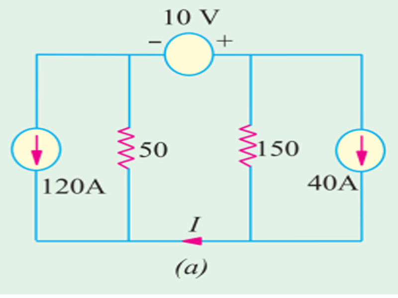
Solution:
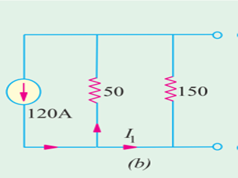
In Fig. 1 (b) Voltage Source has been replace by short circuit and current source by an open
when 120 a source active, Using the current-divider rule, we get I1 = 120 × 50/200 = 30 A.
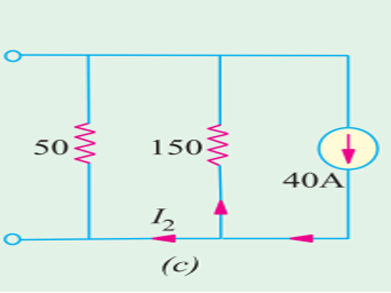
In Fig. 1 (c), only 40 A current source Active, Again, using current-divider rule
I2 = 40 × 150/200 = 30 A.
When 10V Source Active, In Fig. 1(d), only voltage source has been considered. Using Ohm’s law,
I3 = 10/200 = 0.05 A.
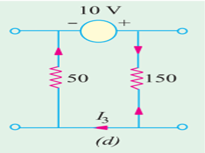
Since I1 and I2 cancel out, I = I3 = 0.05 A. (Answer)