What Is Differential Protection?
Differential protection is a selective protection scheme used to detect faults within a specific zone (like a transformer, generator, busbar, or transmission line) by comparing the incoming and outgoing currents. That operates on the principle of Kirchhoff’s Current Law (KCL), which states that the sum of currents entering a node (or a protected zone) must equal the sum of currents leaving it.

How Differential Protection Works
The core of the system is the differential relay (ANSI device 87), which compares the currents measured by Current Transformers (CTs) at the input and output terminals of the protected equipment.
The basic principle is:
Current entering − Current leaving = Differential Current (Idiff)
Normal Condition or External Fault (No Trip):
- During normal operation (or a fault outside the zone), the current entering the equipment is equal to the current leaving it.
- The relay’s operating coil receives a near-zero differential current.
- The relay remains inactive (stable).
Internal Fault (Trip):
- If a fault occurs inside the protected zone (e.g., a short circuit in a transformer winding), the fault current flows to the fault point, causing the current entering to be unequal to the current leaving.
- This creates a significant, non-zero differential current (Idiff) that flows through the relay’s operating coil.
- If current (Idiff) exceeds the relay’s set threshold, the relay instantly trips the circuit breakers on all sides to isolate the faulty equipment.
Example: Transformer Differential Protection:
Imagine a power transformer connecting a 33 kV side to an 11 kV side.
- Current transformers (CTs) are placed on both sides of the transformer.
- These CTs measure current and send signals to the differential relay.
- The relay compares both currents (after ratio and phase compensation for the transformer vector group).
- If the difference exceeds a preset threshold (due to an internal fault like winding short-circuit), the relay trips both 33 kV and 11 kV breakers.
| Condition | Current In (Iin) | Current Out (Iout) | Differential Current (Idiff) | Relay Action |
| Normal Load | 100A | 100A | ≈ 0A | Restrain (No Trip) |
| External Fault | 500A | 500A | ≈ 0A | Restrain (No Trip) |
| Internal Fault | 500A | 100A | ≈ 400A | Trip |
Result: Only the transformer is isolated the rest of the system keeps running safely.
Note: For a transformer with a turns ratio not equal to 1, the currents are first corrected by the CTs’ ratios so that their secondary currents are equal during normal operation. Modern relays use Percentage Differential Protection (or Biased Differential) to maintain stability during external faults and transient conditions like magnetizing inrush by restraining the trip based on the average through-current.
Differential Protection in Residential Systems
In low-voltage residential and commercial installations, the term “differential protection” is used synonymously with Residual Current Devices (RCDs) or Residual Current Circuit Breakers with Overcurrent Protection (RCBOs). Their purpose is primarily to protect people from electric shock due to earth leakage faults.
Types of Differential Switches (RCDs/RCBOs)
A differential switch monitors the currents in the phase and neutral conductors. If the currents are unequal, it means some current is leaking to the ground (residual current), which can be fatal.
| Type | Protection Against | Typical Application |
| Type AC | Pure sinusoidal alternating residual currents. | Common circuits: standard lighting, conventional heaters, plug sockets without special electronics. |
| Type A | Sinusoidal alternating residual currents and pulsating DC residual currents. | “Specialized” circuits with electronic components: induction hobs, washing machines with speed variation, circuits with dimmer switches. |
| Type F | (Super-Immunized) All Type A faults, plus composite residual currents, and provides a short time delay against network disturbances (transient surges) to prevent nuisance tripping. | Circuits with sensitive electronics: computers, freezers, variable speed drives. |
| Type B | All Type F faults, plus smooth pure DC residual currents. | Specialized industrial applications or electric vehicle (EV) charging stations. |
Major Requirements of Differential Protection:
For power system equipment (transformers, generators, etc.), certain requirements must be met to ensure the protection scheme is both sensitive (trips for internal faults) and stable (does not trip for external faults).
Accurate CT Ratio Matching: For equipment like transformers where the primary and secondary currents are different, the CT ratios must be chosen or compensated for so that the secondary currents fed to the relay are equal under normal through-load.
Correct CT Polarity: The Current Transformers must be connected with correct polarity to ensure the secondary currents cancel out during a healthy condition. Reversed polarity will cause the relay to trip instantly under normal load.
Phase Shift Compensation (for Transformers): Transformers with Delta-Wye (Δ-Y) connections introduce a 30∘ phase shift. The differential relay must compensate for this phase difference, typically by connecting the CTs on one side in a specific configuration (e.g., Delta on the Wye side) or by using internal digital compensation.
Stability against Inrush Current: When a transformer is first energized, it draws a large, transient magnetizing inrush current that is seen only by the primary side. To prevent false tripping, modern relays use Harmonic Restraint, which blocks the trip signal if a large amount of the second harmonic current (a signature of inrush) is detected.
High-Speed Operation: Since internal faults can cause rapid, catastrophic damage, the relay must operate extremely fast (typically within tens of milliseconds) to limit the damage.
Types of Differential Protection:
- Type: Current Differential Protection
Application: Transformers, Generators, Motors, Lines
Description: Compares currents at both ends of the protected zone.
- Type : Voltage Differential Protection
Application: Busbars, Switchgear
Description: Compares voltage at different points.
- Type : Percentage Differential Protection (Biased Differential)
Application: Power Transformers
Description: Adds a restraining current to prevent false trips during external faults or CT saturation.
- Type : Restricted Earth Fault (REF) Protection
Application: Transformers, Generators
Description: Detects earth faults in a limited (restricted) zone using differential principle.
- Type : Differential Switch (RCD/RCCB)
Application: Low-voltage systems
Description: | Disconnects supply when difference between live and neutral currents exceeds a safe limit (protects humans from shock).
Real-Life Analogy
Think of it like a water pipe:
If water entering = water leaving → system is fine.
If some water leaks inside → difference between input and output → leakage detected → automatic valve closes (just like the relay trips!).
Where Differential Protection Schemes are used:
A differential protection scheme (using a differential relay) is a highly sensitive and selective form of protection used to detect internal faults within a specific piece of equipment or a defined protection zone.
Power Transformers: The most common application, protecting against internal faults like winding-to-winding, phase-to-ground, and turn-to-turn short circuits.
Generators and Motors: Used to protect the stator windings from internal faults.
Busbars: Used in substations to provide fast, selective protection for the busbar section, which is a critical node in the system.
Transmission Lines: Applied as Line Current Differential Protection over short to moderate distances, often using fiber optic or pilot wires to compare currents at the two ends of the line.
Working Principle of the Differential Relay
The operation of a differential relay is based on Kirchhoff’s Current Law (KCL), which states that the sum of currents entering a node (or a defined zone) must equal the sum of currents leaving it.
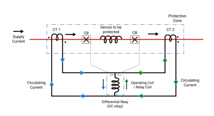
- Current Monitoring: Current transformers (CTs) are placed at the input and output terminals of the equipment being protected, defining the protection zone.
- Current Comparison: The CT secondary currents (which are proportional to the primary currents) are wired to the relay’s operating coil. The connection is made so that, under normal conditions or during an external fault, the incoming and outgoing currents are equal in magnitude (after compensating for ratio differences, phase shifts, etc.) and opposite in direction relative to the relay coil.
- Normal/External Fault Condition:
- The secondary currents circulate between the CTs, but they cancel each other out at the operating coil.
- The resulting differential current () is zero or very close to zero, and the relay does not operate.
Iin−Iout = Id ≈ 0
- Internal Fault Condition:
- When a fault occurs inside the protected zone (e.g., a short circuit in a transformer winding), the current balance is disrupted.
- Currents flow into the fault from both directions, causing a significant differential current () to flow through the relay’s operating coil.
- If exceeds the relay’s preset pick-up value, the relay is activated, sending a trip signal to the circuit breakers to isolate the faulty equipment.Percentage Differential Relays (or Biased Differential Relays) are commonly used to improve stability against false tripping caused by minor current transformer (CT) mismatch or transformer tap changer changes. This type of relay operates only when the differential current () exceeds a certain percentage of the average through current (Restraint current, ).
Behavior During External Faults
An external fault (or through fault) is one that occurs outside the protected zone (e.g., on a feeder connected to the transformer’s secondary side).
- Response: During an external fault, the large fault current flows through the protected equipment (e.g., the transformer).
- Current Balance: The current entering the protection zone is equal to the current leaving the protection zone. Iin = Iout
- Relay Stability: Ideally, the differential current remains zero (≈ 0), and the differential relay remains stable (does not trip).
However, heavy external faults can cause one or more CTs to saturate (lose accuracy) due to the large fault current. This can momentarily result in a false differential current that could cause a simple differential relay to maloperate (false trip). Percentage differential relays are designed to provide restraint proportional to the through-current, making them highly stable and preventing false tripping during heavy external faults, even with CT saturation.
What Happens During Internal Faults:
When a fault occurs inside the protected zone (e.g., inside a transformer winding):
- The current entering and leaving the zone are no longer equal.
- This creates a differential current (Idiff ≠ 0).
- The relay detects the imbalance and sends a trip signal to isolate the faulty equipment.
ANSI Code for the Differential Relay
The American National Standards Institute (ANSI) device number for a Differential Protective Relay is: 87 – Differential Protection Relay.
Common variations are –
| Equipment | ANSI Code |
| Generator Differential | 87G |
| Transformer Differential | 87T |
| Busbar Differential | 87B |
| Line Differential | 87L |
| Motor Differential | 87M |