Half Wave Rectifier Definition:
A Half-Wave Rectifier is the simplest type of rectifier circuit, an essential electronic device that converts Alternating Current (AC) into Pulsating Direct Current (DC).
It achieves this by allowing only one half-cycle (either the positive or the negative) of the input AC waveform to pass through to the load, while blocking the other half.
In simple words:
➡ A half-wave rectifier passes only one half of the AC signal and rejects the other half.
Basic Components of a Half-Wave Rectifier
A simple half-wave rectifier circuit consists of three main components:
- AC Supply
- Provides alternating voltage.
- Usually through a transformer for:
- Voltage step-down (for safety)
- Isolation from mains
- Setting desired output level
- Diode
- The key rectifying element.
- Conducts when forward biased.
- Blocks during reverse bias.
- Common choices:
- 1N4007 (general-purpose)
- 1N4148 (fast switching)
- Schottky diodes (low forward drop)
- Load Resistor (RL)
- Connected across the output.
- Converts electrical energy into useful form (e.g., to power a device).
- Helps in shaping the output.
Optional Components
- Not mandatory, but commonly used.
- To step down high AC mains (220V/110V) to a lower safe value (e.g., 12V AC).
- Capacitor Filter (for smoothing)
- Not part of the “pure” half-wave rectifier.
- Used to reduce ripple.
- Provides smoother DC output.
- Fuse
- For safety to protect the circuit from overload.
Half-Wave Rectifier Working Principle
AC Input Nature
- AC voltage continuously alternates between positive and negative cycles.
- A diode is a unidirectional device, it conducts only when forward biased and blocks when reverse biased.
Operation during Positive Half-Cycle
- During the positive half-cycle, the anode of the diode becomes positive relative to the cathode.
- Diode becomes forward biased.
- Current flows through the diode, load resistor (RL) and returns to the AC source.
- Output across the load is similar to the positive half of the sinusoidal input.
✔ Output obtained: pulsating DC (only positive half).
Operation during Negative Half-Cycle
- During the negative half-cycle, the anode becomes negative relative to the cathode.
- Diode becomes reverse biased.
- No current flows (practically a very tiny leakage).
- Output across the load is zero.
❌ The negative half of the AC waveform is blocked.
Half Wave Rectifier Capacitor Filter:
A half-wave rectifier with capacitor filter is a circuit where a capacitor is connected across the load of a half-wave rectifier to reduce AC ripples and produce a smoother DC output. A capacitor filter is used in a half-wave rectifier to smooth the pulsating DC by storing charge during the conduction period and releasing it during non-conduction. It significantly reduces ripple voltage but still provides poorer regulation than full-wave capacitor filtered rectifiers.
Without Capacitor
- Output is purely pulsating DC.
- Voltage drops to zero during negative half-cycle → high ripple.
With Capacitor Filter
- During the positive half cycle, diode conducts → capacitor charges to peak voltage VmV_mVm.
- During the negative half cycle, diode is reverse biased → capacitor discharges slowly through load RLR_LRL.
- Since it discharges slowly, output never falls to zero, giving smoother DC.
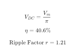
Ripple Factor of Half Wave Rectifier:
Definition
Ripple factor (γ) is a measure of the AC component present in the rectifier output relative to the DC component.
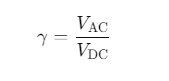
Lower ripple factor → smoother DC output.
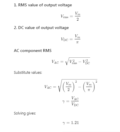
Ripple Factor of Half-Wave Rectifier (Without Filter)
Derivation Result:
γ =1.21
Meaning:
The AC component in the output is 121% of the DC value, which indicates very high ripple.
Derivation:
Efficiency of Half Wave Rectifier:
Definition
Rectification efficiency (η) is the ratio of DC power delivered to the load to the AC power supplied by the transformer (or source).
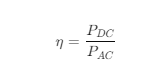
A half-wave rectifier has a maximum efficiency of η=40.6% (or 0.406)
Comparison with Other Rectifiers
| Rectifier Type | Maximum Efficiency |
| Half-wave | 40.6% |
| Full-wave (center-tap) | 81.2% |
| Bridge rectifier | 81.2% |
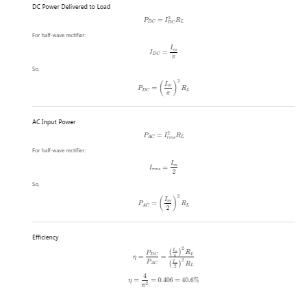
RMS value of Half Wave Rectifier:
The RMS value of a half-wave rectified signal is half of the peak value. RMS value of the half-wave rectified output voltage is Vm/2, and RMS current is Im/2. This RMS value is lower because only one half-cycle of the AC signal contributes to the output.
Derivation:
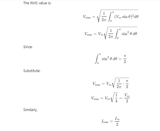
Final Formula (Result):
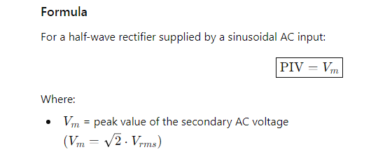
Peak Inverse Voltage (PIV) of a Half-Wave Rectifier
Definition
Peak Inverse Voltage (PIV) is the maximum reverse voltage that appears across the diode when it is reverse biased during the negative half-cycle of the AC input.
During the negative half-cycle, the diode is reverse biased, and:
- The full peak value of the AC input appears across the diode.
- Therefore, the diode must withstand this maximum reverse voltage without breakdown.
Why it Matters
Choosing a diode with PIV less than VmV_m will cause:
- Reverse breakdown
- Damage to the diode
- Failure of the rectifier circuit
Form Factor of Half-Wave Rectifier
Definition
Form Factor is the ratio of the RMS value of the rectified output voltage to its average (DC) value.

Meaning
A form factor greater than 1 indicates that the RMS value is higher compared to the DC value, showing more AC ripple in the output.
⭐ Advantages of Half-Wave Rectifier
1. Simple Circuit Design
- Uses only one diode, making it easy to construct and understand.
2. Low Cost
- Minimal components → very inexpensive and economical for basic applications.
3. Easy to Maintain
- Fewer components mean easier troubleshooting and maintenance.
4. Suitable for Low-Power Applications
- Works fine for small loads where high efficiency is not required.
5. Useful for Signal Processing
- Often used in signal demodulation, peak detection, and clipping
⭐ Disadvantages of Half-Wave Rectifier
1. Low Efficiency (≈ 40.6%)
- Only one half of the AC signal is utilized.
- The negative half is wasted → poor energy conversion.
2. High Ripple Factor (1.21)
- Output is highly pulsating.
- Requires large filters to smooth the output.
3. Low Average Output Voltage
- DC output is lower compared to full-wave rectifiers.
4. Transformer Utilization Factor (TUF) is Poor
- The transformer (if used) works inefficiently because it conducts only half the time.
5. Not Suitable for High-Power Applications
- Cannot deliver smooth, continuous power, so it is limited to small loads.
6. More Harmonic Distortion
- Creates more distortion in power systems compared to full-wave rectification.
⭐ Applications of Half-Wave Rectifier
1. Low-Power DC Power Supplies
- Used where small, simple DC output is required, such as:
- Battery chargers (low-current)
- Night lamps
- Simple LED circuits
2. Signal Demodulation (AM Radio)
- Half-wave rectifiers extract the audio signal from the modulated carrier wave.
3. Peak Detection Circuits
- Used to detect the peak value of AC signals for measurement and analysis.
4. Clipping and Clamping Circuits
- Used in waveform shaping circuits to modify AC waveforms.
5. Testing and Educational Demonstrations
- Ideal for teaching basic rectification concept in labs and academic setups.
6. Pulse Generation
- Used to generate pulse waveforms from sinusoidal AC input.
7. Small Electronic Gadgets
- Useful in toys, alarms, doorbells, and low-power adapters where high performance isn’t required.
⭐ Difference between Half-Wave and Full-Wave Rectifier
| Parameter | Half-Wave Rectifier | Full-Wave Rectifier |
| Number of Diodes | 1 diode | 2 diodes (center-tap) or 4 diodes (bridge) |
| Utilization of AC Wave | Uses only one half-cycle | Uses both half-cycles |
| Output DC Level | Low | Higher |
| Efficiency | 40.6% | 81.2% (approx.) |
| Ripple Factor | 1.21 (high ripple) | 0.48 (much lower ripple) |
| Transformer Utilization | Poor | Better |
| Complexity | Very simple | Moderately complex |
| Output Frequency | Same as input (f) | Twice the input (2f) |
| Applications | Low-power, basic circuits | Power supplies, chargers |
⭐ Short Notes for Exam (2–3 Line Answers)
1. Half-Wave Rectifier
A half-wave rectifier converts only one half-cycle (positive or negative) of AC into pulsating DC using a single diode. It is simple but has low efficiency and high ripple.
2. Full-Wave Rectifier
A full-wave rectifier converts both halves of AC into DC using either a center-tap or bridge diode configuration. It has better efficiency and lower ripple.
3. Ripple Factor
Ripple factor indicates the amount of AC content present in rectified DC output. Lower ripple factor means smoother DC output.
4. Peak Inverse Voltage (PIV)
PIV is the maximum reverse-bias voltage a diode must withstand during the non-conducting half-cycle. It is crucial for selecting proper diodes.
5. Transformer Utilization Factor (TUF)
TUF measures how effectively a transformer is used in a rectifier circuit. Full-wave rectifiers have higher TUF than half-wave rectifiers.
⭐ Lab Report Format: Half-Wave Rectifier
1. Title
Experiment: Study of Half-Wave Rectifier
2. Objective
To design and analyze a half-wave rectifier circuit and observe its output waveform, efficiency, ripple factor, and peak voltage.
3. Apparatus Required
- Diode (1N4007) – 1 pc
- Step-down transformer (230V/12V)
- Load resistor (1 kΩ)
- Breadboard
- Connecting wires
- Oscilloscope / CRO
- Multimeter
4. Theory
A half-wave rectifier allows only the positive half-cycle of AC to pass while blocking the negative half-cycle.
The output is pulsating DC.
Important formulas:
5. Circuit Diagram
(Use the diagram provided above)
6. Procedure
- Connect the transformer to the AC supply.
- Connect the diode in series with the load resistor.
- Connect the CRO across the load.
- Switch on the AC supply.
- Observe input and output waveforms.
- Measure peak voltage, DC output, and ripple.
7. Observations
| Parameter | Measured Value |
| Input Voltage | ___ V |
| Output Voltage | ___ V |
| Peak Voltage | ___ V |
| Load Resistance | ___ Ω |
| Frequency | ___ Hz |
8. Calculations
- Average DC voltage
- RMS value
- Efficiency
- Ripple factor
(Insert calculation steps)
9. Result
The half-wave rectifier was successfully designed and tested.
The observed waveform matches theoretical expectations, showing only the positive half-cycle.
10. Precautions
- Ensure proper diode polarity.
- Do not touch live wires.
- Keep CRO ground properly connected.
11. Applications
- Small DC power supplies
- Signal demodulation
- Clipping circuits
Important Questions & Answers: Half-Wave Rectifier
1. What is a Half-Wave Rectifier?
Answer:
A half-wave rectifier is a circuit that converts AC into DC by allowing only one half-cycle (positive or negative) of the input AC signal to pass through the diode.
2. Which diode is used in a half-wave rectifier and why?
Answer:
A PN junction diode is used because it conducts in the forward direction and blocks current in the reverse direction, enabling AC-to-DC conversion.
3. What is the Peak Inverse Voltage (PIV) of a Half-Wave Rectifier?
Answer:
PIV = Vm, the peak value of the input AC voltage.
This is the maximum reverse voltage the diode must withstand.
What is the average (DC) output voltage of a Half-Wave Rectifier?
Answer: VDC = Vm /π
What is the RMS output voltage of a Half-Wave Rectifier?
Answer: VRMS = Vm / 2
What is the Ripple Factor of a Half-Wave Rectifier?
Answer: Ripple Factor = 1.21
It indicates high AC ripple content in the output.
What is the Form Factor of a Half-Wave Rectifier?
Answer:

Why is the efficiency of Half-Wave Rectifier low?
Answer:
Because it uses only one half of the AC cycle; the other half is wasted.
Efficiency = 40.6% (maximum).
What is diode conduction angle in a half-wave rectifier?
Answer:
The diode conducts for 180° (one half-cycle) of the AC waveform.
What is the Transformer Utilization Factor (TUF)?
Answer:
TUF = 0.287
It shows poor usage of the transformer.
What is the main disadvantage of a Half-Wave Rectifier?
Answer:
It has low efficiency, high ripple, and poor transformer utilization.
Where is a half-wave rectifier used?
Answer:
Used in:
- Low-power DC supplies
- Signal demodulation
- Peak detectors
- Battery chargers (simple circuits)
What is the frequency of output DC for a half-wave rectifier?
Answer:
The output pulsating DC frequency equals the input AC frequency:
fout=finf_{out} = f_{in}fout=fin
What happens during the negative half-cycle of input?
Answer:
The diode is reverse biased and no current flows through the load.
Why is a filter capacitor used in a half-wave rectifier?
Answer:
To reduce ripple, smooth the output, and produce a more constant DC voltage.
Multiple Choice Questions (MCQs)
- A half-wave rectifier uses how many diodes (in the simplest form)?
A) 4 B) 2 C) 1 D) 0
Answer: C) 1 - The average (DC) output voltage VDC of an ideal half-wave rectifier with peak input Vm is:
A) Vm/2 B) Vm/π C) 2Vm/π D) Vm/ √2
Answer: B) Vm/π - The ripple factor r of an ideal half-wave rectifier (no filter) is approximately:
A) 0.48 B) 0.21 C) 1.21 D) 0.707
Answer: C) 1.21 - The theoretical maximum efficiency of an ideal half-wave rectifier is about:
A) 100% B) 81.2% C) 40.53% D) 25%
Answer: C) 40.53% (≈ 4/π²) - Peak Inverse Voltage (PIV) for the diode in a simple half-wave rectifier equals (ideal transformer isolated secondary):
A) 0 V B) Vm (peak) C) 2Vm D) Vm/2
Answer: B) Vm (peak) - Which application is MOST appropriate for a half-wave rectifier?
A) High-power SMPS primary rectification B) Precision low-ripple DC supply for digital electronics
C) Simple peak detection / AM demodulation D) Large battery charging at high current
Answer: C) Simple peak detection / AM demodulation - If you reverse the diode polarity in a half-wave rectifier, the output will be:
A) Short circuit B) Negative half-cycles passed (i.e., inverted) C) No change D) Full-wave output
Answer: B) Negative half-cycles passed (i.e., inverted) - For the same secondary peak Vm, the DC output of an ideal full-wave rectifier is:
A) Equal to half-wave VDC B) Twice the half-wave VDC C) Half of Vm D) Zero
Answer: B) Twice the half-wave VDC - Transformer Utilization Factor (TUF) for half-wave vs full-wave: which is true?
A) Half-wave has better TUF than full-wave
B) Full-wave has better TUF than half-wave
C) Both equal
D) TUF is irrelevant to rectifiers
Answer: B) Full-wave has better TUF than half-wave - If the diode forward drop Vf is not negligible, the practical peak of the output pulse is approximately:
A) Vm B) Vm−Vf C) Vf D) 0
Answer: B) Vm−Vf