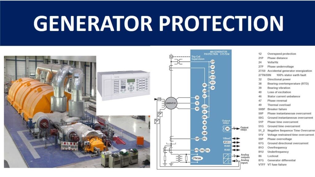
Generator Protection
Definition
Generator protection refers to the system of relays, sensors, and control mechanisms used to detect abnormal operating conditions in electrical generators and isolate them before they experience damage or cause system instability.
A generator is a critical and expensive asset, and failures can lead to severe mechanical damage, environmental hazards, and long outages. Protection schemes ensure:
- Safety of equipment and personnel
- Maintaining system stability
- Preventing extended outages
- Reducing repair costs
Why Generator Protection Is Needed
Generators face various threats, such as:
- Electrical faults (internal/external)
- Overheating
- Overcurrent or short circuits
- Mechanical failures (bearing issues, turbine problems)
- Unstable system conditions
- Loss of excitation or synchronization issues
Therefore, multiple coordinated protection systems are required.
Types of Generator Protection
Stator Winding Protection
a) Differential Protection (87G)
- Detects internal phase-to-phase or phase-to-ground faults.
- Measures the difference in current entering and leaving the stator windings.
- If difference > threshold ⇒ internal fault, trip generator.
Most sensitive and primary protection for internal faults.
b) Stator Ground Fault Protection (64G)
Protects against ground faults, which are the most common generator faults.
Methods include:
- Low-Resistance Grounding System
- High-Resistance Grounding
- 100% stator ground fault protection using 3rd harmonic voltage
Rotor Protection
a) Rotor Earth Fault Protection (64R)
- Detects insulation failure in rotor windings.
- Rotor faults increase heating and can damage the field winding.
b) Rotor Overheating Protection
- Caused by overdrive, excitation issues, shorted turns, or ventilation failures.
- Monitored using temperature detectors and thermal models.
C) Overcurrent Protection (50/51)
- Protects generator terminals and step-up transformer.
- Common during external faults or overloads.
- Backup protection for differential and distance protection.
D) Overvoltage Protection (59)
- Caused by sudden load rejection or excitation faults.
- Protects insulation from excessive dielectric stress.
E) Undervoltage Protection (27)
- Detects loss of load or system issues.
- Used to protect auxiliary systems and prevent motoring effect.
F) Overfrequency and Underfrequency Protection (81O / 81U)
- Overfrequency may occur during sudden loss of load.
- Underfrequency occurs when generation < demand.
- Protects the shaft against mechanical stress due to speed variations.
G) Reverse Power Protection (32)
- Prevents the generator from operating as a motor.
- When turbine input power fails, the generator may draw power from the grid.
- Protects prime mover (steam turbine, diesel engine) from overheating.
H) Loss of Excitation Protection (40)
- Occurs when excitation system fails.
- Generator acts like an induction generator.
- Causes high stator current and rotor heating.
- Detected using impedance measurement.
I) Overexcitation Protection (24)
- Measures volts-per-hertz (V/Hz ratio).
- Overexcitation overheats the core and stator.
J) Negative Phase Sequence Protection (46)
- Detects unbalanced loads or phase faults.
- Negative sequence currents cause severe rotor heating.
- Critical for large generators.
K) Out-of-Step (Loss of Synchronism) Protection (78)
- Protects generator during large power swings.
- Disconnects the generator when it loses synchronism with the grid.
L) Overspeed Protection
- Typically used for turbine-generator units.
- Triggered by sudden load rejection.
- Uses mechanical or electronic speed detectors to trip turbine valves.
M) Temperature Protection
Includes:
- Stator temperature (RTDs)
- Bearing temperature
- Cooling system failure
Trips generator if overheating occurs.
N) Generator Transformer Protection
- Differential protection (87T)
- Buchholz relay (gas accumulation)
- Overcurrent and thermal overload relays
Important because generator-transformer is considered a unit protection zone.
Unbalanced Stator Loading Protection
Definition
Unbalanced stator loading protection protects a synchronous generator from the harmful effects of unbalanced currents caused by uneven loading or asymmetrical faults in the power system.
Unbalanced loading generates negative sequence currents (I₂) that produce a reverse-rotating magnetic field. This rotating field induces double-frequency currents in the rotor, causing severe heating.
This protection is implemented by a Negative Phase Sequence (NPS) relay.
Why Unbalanced Loading Is Dangerous
When the load on the generator phases is not equal, the system becomes unbalanced. This produces negative phase sequence currents, which:
- Rotate opposite to the rotor’s direction
- Cut the rotor at twice synchronous frequency
- Induce high eddy currents in rotor body, field winding, retaining rings
- Cause rapid overheating of the rotor
- Can damage insulation and endangers generator life
Large generators are particularly sensitive to this because of their low thermal capacity.
Sources of Unbalanced Stator Loading
- Single-phase loads
Large industrial single-phase loads or railway traction.
- Unbalanced three-phase loads
Unequal supply to different phases.
- Asymmetrical faults
- Single line-to-ground fault (L-G)
- Line-to-line fault (L-L)
- Double line-to-ground fault (L-L-G)
- Open phase conditions
Due to broken conductors, fuse failures.
- System voltage unbalance
Transmission line unbalance or transformer issues.
Principle of Operation
The relay measures the negative sequence component of the current (I₂).
If I₂ exceeds a preset limit for a certain time, the relay operates and trips the generator.
The heating effect caused by I₂ is proportional to:
I22⋅t
So, protection uses an I₂²t characteristic, similar to thermal overload protection.
Negative Phase Sequence Relay (Relay Code: 46)
Function
- Continuously monitors the negative-sequence current.
- Compares it with permissible limits set by the generator manufacturer.
- Triggers alarm or trip based on severity.
Settings
Typical settings:
Alarm:
When I₂ exceeds 10% of rated current for a few seconds.
Trip:
When I₂ exceeds 15–20% of rated current depending on machine design.
Manufacturers specify an I₂²t limit, such as:
I22⋅t = 40
Which means:
At 10% I₂ → permissible t = 40 / (0.1²) = 4000 sec
At 30% I₂ → permissible t = 40 / (0.3²) = 444 sec
Relay Operating Characteristics
The relay commonly uses:
- Definite time characteristic
Trips after fixed time when I₂ exceeds threshold.
- Inverse time (I₂²t) characteristic
Trips faster for higher unbalance.
- Two-stage protection
- Stage 1: Alarm
- Stage 2: Trip
Protection Scheme Components
- Negative sequence current filter
Extracts I₂ component from overall current. - Measuring element
Compares I₂ value to threshold. - Timing element
Computes I₂²t. - Tripping element
Trips generator breaker or reduces load. - Alarm output
For moderate unbalance levels.
Coordination With Other Protections
Unbalanced stator loading protection works with:
- Stator overcurrent protection
- Distance protection
- Transformer differential protection
- System unbalance protection
It is not a substitute for primary fault protection but acts as secondary, thermal-based safety for rotor.
Advantages
- Prevents thermal damage to rotor.
- Detects both external faults and load unbalances.
- Fast and accurate response to asymmetrical conditions.
- Helps maintain generator lifespan.
Stator Winding Differential protection (87G)
Differential protection (87G) is the primary protection method for detecting internal faults within the stator windings of a generator. It compares the currents entering and leaving the generator stator.
If the difference exceeds a preset value, an internal fault is detected and the relay trips the generator.
This is the most important stator protection and provides fast, selective, and highly sensitive fault detection.
Why Stator Differential Protection Is Needed
A generator’s stator windings are vulnerable to:
- Phase-to-phase faults
- Phase-to-ground faults
- Winding short circuits
- Turn-to-turn faults
- Internal insulation failure
These faults produce very high currents and can lead to:
- Severe mechanical damage
- Burning of windings
- Core damage
- Long outages
Therefore, a fast and secure protection like differential protection is essential.
Principle of Operation
Based on Kirchhoff’s Current Law (KCL):
Iin = Iout
Under normal operating conditions, the sum of currents entering the protected zone equals the sum of currents leaving.
Differential current is calculated as:
Idiff = Iin −Iout
- If Idiff ≈ 0 → no internal fault
- If Idiff > setting → internal fault → trip
The protection operates only for internal faults, not for external faults.
Protection Zone
The differential protection zone includes:
- Stator winding terminals
- Generator step-up transformer (if unit-connected)
- Neutral grounding equipment
CTs are placed at both ends of the stator windings to measure input and output currents.
Types of Differential Schemes
- Merz-Price Circulating Current Scheme
Most commonly used.
- CTs are installed on both ends of the generator stator
- Secondary currents circulate through a relay
- Any difference activates the relay
- Biased (Percentage) Differential Protection
Used to prevent false tripping due to:
- CT errors
- Magnetic saturation
- Inrush currents from transformer (if in same zone)
Internal vs External Fault Behavior
Internal fault
- Large difference between input and output currents.
- Relay detects high Idiff.
- Immediate trip of generator breaker.
External fault
- Both CTs measure same fault current.
- Iin ≈ Iout → Idiff ≈ 0.
- Relay remains stable (no trip).
Applications
Widely used in:
- Power plant generators
- Hydroelectric generators
- Thermal plant alternators
- Turbo-generators
- Gas-turbine generators
Especially in unit-connected generator-transformer sets.
Advantages of Differential Protection (87G)
- Fast operation (20–40 ms)
- Highly selective (only trips for internal faults)
- Sensitive to small winding failures
- Stable during external faults or overloads
- Accurate even with CT errors (biased differential)
Limitations
- CT mismatch can cause false trips (minimized by biasing)
- Cannot detect faults outside the protected zone
- Requires multiple CTs and correct wiring
- Expensive compared to simpler protections
Typical Settings
- Differential pickup level: 20–30% of rated current
- Bias slope: 15–30%
- Operating time: instantaneous or <40 ms
tator Ground Fault Protection (64G)
Definition
Stator Ground Fault Protection (64G) protects the generator stator windings from phase-to-ground faults, which are the most common type of generator faults.
This protection detects insulation failure that allows one stator phase to make contact with ground.
Ground faults can:
- Damage stator core and windings
- Escalate to severe arcing faults
- Cause long outages
- Lead to expensive repairs
Thus, 64G is essential in all generator protection systems.
Why Ground Fault Protection Is Necessary
A stator ground fault causes:
- Very high fault currents (in low-resistance grounded systems)
- Thermal and mechanical damage
- Hot spots in iron core
- Overheating of stator laminations
- Melting of copper conductors
Generators are usually grounded through impedance (resistor or transformer).
This limits the fault current but still requires sensitive fault detection.
Types of Grounding & Their Impact on Protection
- Low-Resistance Grounded Generators
- Allows 200–400 A of ground fault current.
- Easier detection.
- High-Resistance Grounded Generators
- Limits current to 5–15 A.
- Requires more sensitive detection schemes.
- Ungrounded or Impedance-Grounded Systems
- Detection is more challenging.
- Special methods (3rd harmonic, injection) are needed.
Types of Stator Ground Fault Protection (64G)
- 95% Ground Fault Protection (59N or 64G)
Covers 95% of the stator winding from the terminal end.
Operating Principle:
- Measures zero-sequence voltage (59N)
- Detects ground faults near generator terminals
- Fast operation
Limitation:
- Cannot detect faults near the neutral point (last 5% of winding)
- 100% Stator Ground Fault Protection (Third Harmonic Voltage Method)
This method protects the entire stator winding, including the neutral area.
Principle:
During normal operation, 3rd harmonic voltages are present in the stator winding and distributed unevenly:
- High at terminals
- Low at neutral
But during a ground fault:
- Voltage pattern changes abruptly
- Relay detects the change in 3rd harmonic voltage ratio between terminal and neutral
Advantages:
- Provides complete 100% coverage
- Very sensitive
Limitations:
- Depends on machine loading
- Not suitable at very low loads (may need blocking)
- 100% Ground Fault Protection (Injection Method – 64S, 64R)
Used in modern digital relays.
Types of injection:
- Low-frequency injection (20–60 Hz)
- DC injection method
Principle:
- A small voltage or current is injected into the neutral
- Relay monitors the return path
- Any fault to ground changes the impedance
Advantages:
- Very reliable
- Works at all loads, even at standstill
- Neutral Overcurrent Protection (51N, 64N)
Used in low-resistance grounded systems.
Principle:
- Measures neutral grounding resistor current
- High ground current = stator ground fault
- Quick detection
Limitation:
- Cannot detect faults very close to neutral (low voltage)
Protection Zones
Different techniques protect specific areas:
| Method | Coverage | Suitable For |
| 59N / 64G | 90–95% | All generators |
| Third harmonic | 100% | Large generators |
| Injection method | 100% | High-resistance/ungrounded |
| Neutral OC 51N | 80–90% | Low-resistance grounded |
Relay Types Used
- Zero-sequence overvoltage relay (59N)
- Neutral overcurrent relay (51N)
- Third harmonic voltage relay (64G2 / 64G-T)
- Injection-based relays (64S / 64R)
Modern digital relays combine several of these for reliable, 100% coverage.
Typical Settings
- Zero-sequence pickup: 5–10% of rated voltage
- Neutral overcurrent: based on grounding resistor rating
- 3rd harmonic thresholds: ratio-based (adaptive)
Advantages of Stator Ground Fault Protection
- Fast and sensitive
- Prevents severe stator damage
- Can provide full 100% winding coverage
- Works with various grounding methods
- Reliable even under low-load conditions (with injection)
Related Article:
What happens if a generator is run under-excited?
Basics concept of Synchronous Generators / alternator for Beginners
What happens if a generator is run under excited or over excited ?
How Differential Protection Works And ANSI Code
What Is Generator Protection and Why Is It Important?
Basic concept of different types of Relays
Over Current Relay Working Principle, Types and Applications