Generator Protection
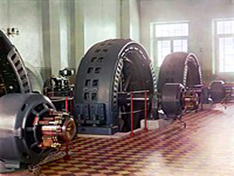
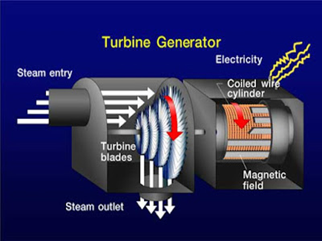
The synchronous generator, the heart of any power generation facility, is a marvel of engineering, converting mechanical energy into the electrical lifeblood of modern society. However, this intricate and expensive asset is susceptible to a variety of internal and external faults that can lead to catastrophic failures, costly repairs, and prolonged outages. To ensure its reliability and longevity, a sophisticated and multi-faceted protection system is employed. This system is not a single entity but a coordinated suite of relays and schemes designed to detect specific abnormal conditions with speed and selectivity. This in-depth analysis explores the critical Generator Protection schemes implemented to safeguard generators against the most common and damaging faults:
- Stator Earth Faults,
- Rotor Earth Faults,
- Stator Short Circuits,
- Stator/Rotor Interturn faults,
- Unit transformer faults,
- External faults)
Here is a detailed explanation of generator protection mechanisms focusing on the major fault types:
Generator Protection: Key Fault Types & Protective Measures
Large electrical generators are critical assets in power systems. They require robust Generator Protection systems to detect and isolate faults quickly, minimizing equipment damage and system instability. Key protection areas include:
Stator Earth Faults (Ground Faults):
Occurs when one phase of the stator winding comes into contact with earth (ground) or the stator core due to insulation failure.
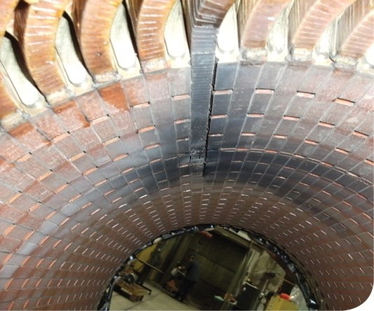
The stator winding, a complex array of insulated copper bars housed within the generator’s core, is where the electrical power is generated. A breakdown of this insulation to the earthed stator core results in a stator earth fault. The severity of such a fault is largely dictated by the method of neutral grounding. In most large generators, the neutral point is grounded through a high impedance (either a resistor or a distribution transformer with a secondary loading resistor). This technique, known as high-impedance grounding, intentionally limits the fault current to a few amperes (typically 5-25A). While this minimizes immediate damage to the stator core from the fault arc, it makes detection more challenging as the fault current is not significantly different from normal load currents.
Causes:
- Moisture ingress
- Insulation aging or mechanical damage
- Conductor overheating
Protection Methods:
- 59N / 64G– Neutral overvoltage protection (detects ground faults via voltage build-up)
- 64S– 100% stator earth fault protection using third harmonic voltage (detects faults along the entire winding)
- 59GN – Zero-sequence voltage detection
- Neutral Grounding Resistor (NGR) Monitoring
Explanation:
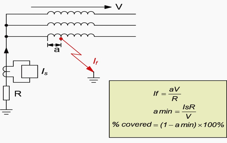
95% Winding Protection (Neutral Overvoltage Relay – 59N): The most common scheme for high-impedance grounded generators relies on detecting the voltage rise at the generator’s neutral point during an earth fault. When an earth fault occurs, the generator’s phase-to-ground voltage at the fault location collapses, causing the neutral point, which is normally near zero potential, to shift. A voltage transformer connected between the generator neutral and ground measures this voltage. The secondary of this transformer is connected to an overvoltage relay (ANSI device number 59N). If the neutral voltage exceeds a preset threshold (typically 5-10% of the normal phase-to-neutral voltage), the relay operates, tripping the generator. This simple and reliable scheme effectively protects about 95% of the stator winding, from the phase terminals down towards the neutral. It cannot, however, detect faults very close to the neutral point, as the voltage shift produced by these faults is too small to be reliably distinguished from normal system imbalances.
100% Winding Protection (Third Harmonic or Injection Methods): Leaving the last 5% of the winding near the neutral point unprotected is an unacceptable risk. To cover this “dead zone,” more sensitive and specialized techniques are employed.
- Third Harmonic Detection: All synchronous generators naturally produce third harmonic voltages (150 Hz in a 50 Hz system, 180 Hz in a 60 Hz system). These voltages are in phase and are therefore present at the neutral point. During normal operation, a measurable third harmonic voltage exists between the neutral and the phase terminals. An earth fault near the neutral will short-circuit this path, causing a significant change (either an increase or decrease, depending on the scheme) in the third harmonic voltage measured at the neutral or terminals. Relays are configured to detect this deviation from the norm and initiate a trip.
- Signal Injection: The most modern and reliable method for 100% stator earth fault protection involves injecting a low-frequency (typically 15-25 Hz) or coded DC voltage into the generator’s neutral via a coupling transformer. A sensitive relay continuously measures the current flowing due to this injected voltage. During normal operation, this current is near zero as there is no return path. When an earth fault occurs anywhere in the winding, a path for the injected current is created through the fault to ground. The relay detects this current flow and trips the generator. This method is independent of machine loading and provides complete, sensitive protection for the entire stator winding.
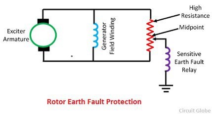
Rotor Earth Faults
Occurs when the DC excitation circuit (rotor winding) contacts the rotor body (earth), causing imbalance in the excitation system.
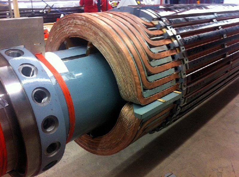
The rotor, or field winding, is a DC circuit that creates the magnetic field necessary for generation. A rotor earth fault occurs when the insulation of the rotor winding breaks down, creating a connection to the forged steel rotor body. A single rotor earth fault does not immediately cause a major problem or draw significant fault current, as the DC circuit is normally isolated from the ground. However, it creates a dangerous latent condition. A second rotor earth fault would short-out a portion of the field winding. This would create a magnetic imbalance, leading to severe mechanical vibrations that could destroy the generator bearings and the entire machine in seconds. Furthermore, the intense arcing from the short circuit could cause severe damage to the rotor forging itself.
Rotor Earth Faults Types:
- Earth Fault in Field Circuit
- Field Circuit is Not Earthed
- First Earth Fault is not Harmful
- 2nd earth fault can cause serious damage of the generator
Causes:
- Brush or slip ring wear
- Aging insulation
- Vibration or mechanical deformation
Protection Methods:
- 64F (Field Ground Relay) – Detects insulation failure in rotor circuit using a DC or AC injection method
- Two-stage rotor earth fault detection – First fault alarmed, second fault trips
Note: One earth fault in the rotor is usually tolerated temporarily, but a second can cause a shorted loop and serious damage.
Explanation of Rotor Earth Faults (64R):
Because a single earth fault is benign but a second is catastrophic, continuous monitoring for the first fault is essential. This is accomplished using rotor earth fault relays (ANSI device 64R).
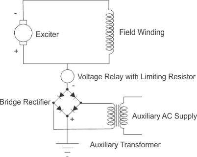
- DC Injection Method: A common technique involves applying a DC voltage bias to the field winding through a high resistance. One side of this DC source is connected to the field winding, and the other is connected to the station ground. A sensitive overcurrent or under voltage relay is included in this circuit. If an earth fault occurs on the rotor, a current path is established from the injection point, through the relay, through the fault, and back to the ground, causing the relay to operate. Modern microprocessor-based relays use a coded or pulsed DC injection to improve sensitivity and avoid issues with DC offset voltages.
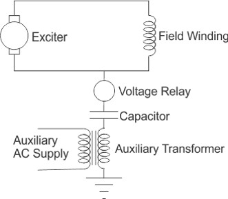
- AC Injection Method: An alternative method involves injecting a low-frequency AC voltage (similar to the stator injection method) onto the field winding. The resulting AC current flow to ground is monitored. The presence of a fault creates a path for this current, which is detected by a sensitive relay. This method offers high sensitivity and is immune to DC interference.
Stator Phase-to-Phase Short Circuits (Stator Short Circuits)
A short circuit between two or three phases in the stator winding, leading to large fault currents.
Stator short circuits, or phase-to-phase faults, are among the most severe and damaging faults. They involve a low-impedance connection between two or three of the stator phases. These faults result in extremely high currents, thousands of times the normal load current, flowing through the windings. The immense electromagnetic forces generated can physically deform and destroy the windings, while the intense heat can melt the copper conductors and vaporize the insulation almost instantaneously. Speed of detection and clearance is paramount.
Causes:
- Severe insulation failure
- Overloading or mechanical damage
- Manufacturing defects
Protection Methods:
- 87G– Differential protection (compares current entering and leaving the stator winding)
- 51/50 – Overcurrent protection (backup)
- 21– Distance protection (less common for internal generator faults)
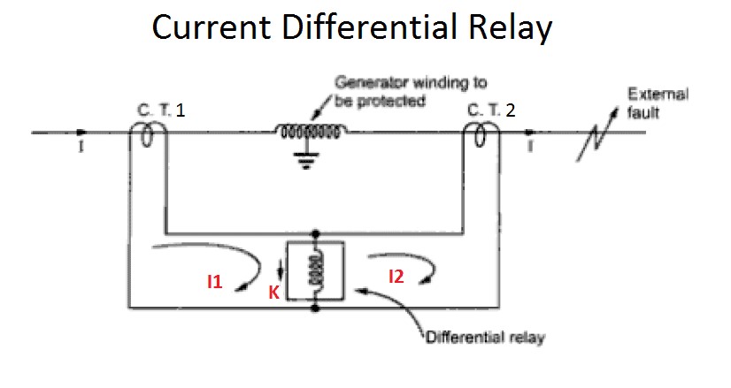
Explanation of Stator Short Circuits:
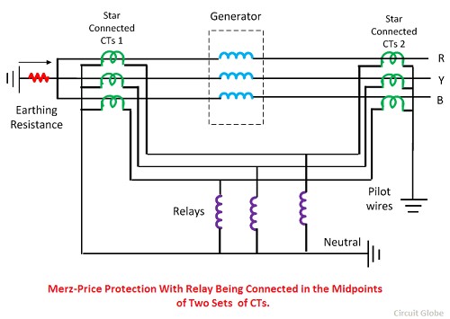
- Generator Differential Protection (87G): The primary Generator Protection against stator phase faults is the high-speed differential relay. This scheme works on the principle of Kirchhoff’s Current Law: the current entering a winding must equal the current leaving it. Current transformers (CTs) of identical ratios are installed at both the neutral and terminal ends of each stator phase winding. The secondary windings of these CTs are connected in opposition. During normal operation or for an external fault, the currents at both ends are equal, and no current flows through the differential relay’s operating coil. If an internal phase fault occurs, the current at the two ends will no longer be equal, creating a differential current that flows through the relay’s operating coil. If this differential current exceeds a predefined setting, the relay operates instantaneously (typically within 20-30 milliseconds) to trip the generator breaker, the field breaker, and the turbine.
- Backup Protection (Impedance/Distance and Overcurrent Relays): In the unlikely event that the differential relay fails, backup protection is essential.
- Impedance Relays (21): These relays measure the impedance seen from the generator terminals. For an internal fault, the measured impedance will be very low. The relay is set to operate if the impedance falls within a predefined zone that covers the generator and sometimes part of the step-up transformer.
- Voltage-Restrained/Controlled Overcurrent Relays (51V): These relays combine overcurrent measurement with a voltage element. During a fault, the current increases while the terminal voltage collapses. The relay is set to be more sensitive (i.e., trip at a lower current) when the voltage is low. This prevents the relay from tripping on high load currents (where voltage is normal) but ensures fast operation for close-in faults.
Differential Generator Protection is the primary method for detecting internal short circuits in stator windings.
Stator/Rotor Interturn Faults
Fault between turns of the same winding phase, either in the stator or rotor, without involving earth.
An interturn fault is a short circuit between adjacent turns of the same phase winding in the stator or rotor. These are particularly insidious faults because they begin with very small fault currents, making them extremely difficult to detect with standard phase fault protection like the 87G relay, which looks for an imbalance between the ends of the entire winding. If left undetected, even a small interturn fault will generate intense localized heat, rapidly degrading the insulation and escalating into a much more severe phase-to-ground or phase-to-phase fault.

Causes:
- Excessive mechanical stress
- Insulation failure between adjacent turns
- Overheating and vibration
Protection Methods:
- Negative Sequence Current Protection (46) – Detects unbalanced currents caused by asymmetry
- Thermal Monitoring – Infrared or embedded sensors
- Specialized Interturn Protection Relays (using partial discharge monitoring, zero-sequence current differential)
Note: Rotor interturn faults may cause vibrations or magnetic imbalance affecting the generator and nearby equipment.
Explanation of Interturn Faults:
- Stator Interturn Faults: For generators with multi-turn coils and parallel winding paths, split-phase protection or transverse differential protection can be used. This involves comparing the current in the parallel paths of a single phase. If an interturn fault occurs in one path, the current distribution becomes unbalanced, and a differential current is detected by a sensitive relay. For machines without parallel windings, detection is much harder and often relies on advanced online monitoring of partial discharges or air gap magnetic flux.
- Rotor Interturn Faults: These are even more challenging to detect electrically. A shorted turn in the field winding causes a slight change in the total field impedance and current. While some advanced relays attempt to monitor this, the change is often too small to be reliably detected. The most common method of detection is through non-electrical means, such as monitoring for increases in generator vibration caused by the magnetic imbalance from the shorted turn.
Unit Transformer Faults:
The unit transformer steps up generator voltage to transmission level. Internal or external faults can occur.
Large generators are typically connected to the power system through a dedicated generator step-up (GSU) transformer. The low-voltage bus connecting the generator to this transformer often has a tap-off to a unit auxiliary transformer (UAT), which supplies power to the power plant’s own equipment. Faults within these transformers must be cleared quickly to protect both the transformer and the generator.
Causes:
- Insulation breakdown
- Oil contamination
- Bushing failure
- Thermal aging
Protection Methods:
- 87T– Transformer differential protection
- 63– Buchholz relay (for gas detection in oil-filled transformers)
- 49 – Thermal overload protection
- 51/50 – Backup overcurrent protection
Transformers often share protection zones with the generator in unit protection schemes, requiring coordination.
Protection Schemes for Unit Transformer Faults:
The protection for the generator and its associated transformers is often integrated into an overall differential scheme (87U or 87O). This scheme extends the zone of protection to include the generator, the GSU, and sometimes the UAT. It compares the currents entering and leaving this entire zone. The CTs on the high-voltage side of the GSU must be of a different ratio and connection (e.g., delta-connected to compensate for the wye-delta phase shift of the transformer) to be compared with the generator-side CTs. This scheme provides fast and sensitive protection for any fault within this combined generator-transformer unit. The GSU and UAT will also have their own dedicated protection, such as Buchholz relays (detecting gas accumulation from internal arcing) and pressure relief devices.
External Faults:
Short circuits or abnormal conditions in the network **outside** the generator zone (e.g., transmission line faults).
While the generator must be disconnected for internal faults, it must also be protected from damaging conditions originating on the external power system. It is generally required to “ride through” transient external faults but must be disconnected if the fault persists or if system conditions become hazardous to the machine.
Risk:
- External faults can cause thermal and mechanical stress due to prolonged high currents and voltage dips.
Protection Methods:
- Backup Distance Protection (21)– Detects faults on nearby transmission lines
- Overcurrent Relays (51) – Time-delayed to coordinate with downstream devices
- Generator Under/Overvoltage (27/59) – Detects abnormal supply conditions
- Out-of-Step Protection (78)– Prevents damage during power swings
Protection Schemes for External Faults:
- Backup Impedance (Distance) Relays (21): As mentioned earlier, these relays provide time-delayed backup protection for uncleared faults on the connected transmission lines.
- Negative Phase Sequence Protection (46): Unbalanced system faults or loads cause negative sequence currents to flow. These currents induce double-frequency currents in the rotor, leading to rapid and dangerous overheating of the rotor body and damper windings. A negative sequence relay monitors these currents and will trip the generator based on an inverse-time characteristic (I22t=K), allowing it to withstand small imbalances for longer periods but tripping it very quickly for severe imbalances.
- Out-of-Step (Pole Slip) Protection (78): If the generator loses synchronism with the rest of the power system, it will experience large current and voltage swings and severe mechanical torque pulsations. This “pole slipping” is extremely stressful. An out-of-step relay detects this condition by monitoring the rate of change of the impedance seen at the generator terminals and trips the machine to prevent catastrophic damage.
The generator must not trip for all external faults unless it’s at risk. Discrimination and stability are crucial.
Additional Protections in Generator Systems:
- Over voltage (59) / Under voltage (27) – Grid instability detection
- Over frequency (81O) / Under frequency (81U) – System imbalance protection
- Loss of Excitation (40) – Detects generator operating as induction generator
- Reverse Power (32) – Detects motoring condition (prime mover failure)
- Negative Sequence Protection (46) –
- Due to unbalance stator current
- Backup protection for Generator
- Outside Generator: Cleared by line protection
- Inside Generator: Cleared by Differential or Earth fault protection
Abnormal operating condition
- overcurrent/overload
- Unbalanced load
- Unbalance Current or Negative Sequence Current (Overheating of rotor)
- Over temperature
- Over- and under voltage
- Over- and under excitation
- Over- and under frequency (High vibration in Turbine)
- Over-fluxing
- Asynchronous running
- Generator motoring or Reverse Power (LP turbine blade overheating)
- Failures in the machine control system (i.e. AVR or governor failure)
- Failures in the machine cooling system
- Failures in the primary equipment (i.e. breaker head flashover)
- Open phase
In conclusion, the protection of a synchronous generator is a complex and critical discipline. It requires a deep understanding of the machine’s construction and behavior under both normal and fault conditions. Through the coordinated application of differential, over current, impedance, voltage, and specialized relays, engineers create a robust and reliable shield, ensuring that this vital asset is safeguarded from the myriad threats it faces, thereby guaranteeing the stability and security of our power supply.
Click Here for MCQ Quiz Test:
Synchronous generator ( alternator) MCQ Part -01
Synchronous generator ( alternator) MCQ Part -02
Synchronous generator ( alternator) MCQ Part -03
Synchronous generator ( alternator) MCQ Part -04
Synchronous generator ( alternator) MCQ Part -05
Synchronous generator ( alternator) MCQ Part -06