Definition of Full Wave Rectifier
A Full Wave Rectifier (FWR) is an electronic circuit that converts the entire alternating current (AC) input waveform into a unidirectional direct current (DC) output by utilizing both the positive and negative half-cycles of the AC supply. Unlike a half-wave rectifier, which allows only one half of the input waveform to pass through the load, a full wave rectifier makes use of both halves, resulting in higher efficiency, lower ripple content, and a smoother DC output.
A full wave rectifier can be implemented in two common ways:
- Center-tapped full wave rectifier (using two diodes and a center-tapped transformer)
- Bridge rectifier (using four diodes without a center-tapped transformer)
Because of its improved performance, the full wave rectifier is widely used in power supply units for electronic and electrical systems.
Basic Components of a Full Wave Rectifier
A typical full wave rectifier consists of the following components:
- AC Input Source – Provides the alternating voltage to be converted.
- Transformer – Steps up or steps down the AC voltage to the desired level. In a center-tapped rectifier, the transformer has a center tap on the secondary winding.
- Diodes – Semiconductor devices that allow current to flow in only one direction.
- Load Resistance (RL) – The component across which the rectified output voltage is obtained.
- Filter Circuit (optional) – Used to reduce ripple and smooth the DC output.
Working Principle of Full Wave Rectifier
The working principle of a full-wave rectifier is based on the unidirectional conduction property of diodes. The circuit is arranged in such a way that current through the load always flows in the same direction, irrespective of the polarity of the AC input.
Although the input AC voltage alternates between positive and negative half-cycles, the rectifier circuit inverts the negative half-cycle so that it appears as a positive output across the load. As a result, the output waveform consists of pulsating DC with twice the frequency of the input AC supply.
Note: The user request mentioned “Positive Half-cycle and Positive Half-cycle”; in practice, the operation is described for Positive Half-cycle and Negative Half-cycle.
Center-Tapped Full Wave Rectifier –
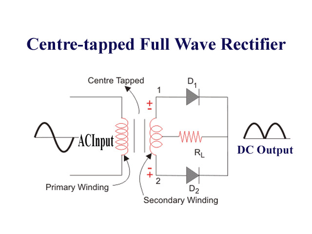
During the Positive Half-Cycle
During the positive half-cycle of the AC input, the center-tapped full wave rectifier operates as follows:
When the upper end of the transformer secondary winding becomes positive with respect to the center tap, diode D1 becomes forward biased.
At the same time, diode D2 is reverse biased and does not conduct.
Current flows from the upper secondary terminal → diode D1 → load resistance (RL) → center tap of the transformer.
The current through the load flows in one direction only, producing a positive voltage across the load.
Thus, during the positive half-cycle, only one diode conducts, and rectification takes place.
In the positive half-cycle, the center-tapped full wave rectifier allows current through diode D1 only, ensuring a unidirectional (DC) output across the load.
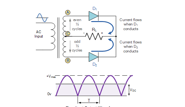
During the Negative Half-Cycle
During the negative half-cycle of the AC input, the center-tapped full wave rectifier operates as follows:
When the lower end of the transformer secondary winding becomes positive with respect to the center tap, diode D2 becomes forward biased.
At the same time, diode D1 is reverse biased and does not conduct.
Current flows from the lower secondary terminal → diode D2 → load resistance (RL) → center tap.
The current through the load flows in the same direction as during the positive half-cycle, producing a positive voltage across the load.
During the negative half-cycle, the conducting diode switches from D1 to D2, but the load current remains unidirectional, allowing the rectifier to utilize both halves of the AC input and produce pulsating DC.
Bridge Rectifier
During the positive half-cycle of the AC input, the bridge rectifier operates as follows:
When the upper terminal of the AC supply becomes positive with respect to the lower terminal, two diagonally opposite diodes in the bridge become forward biased.
Typically, diode D1 and diode D3 conduct, while the other two diodes (D2 and D4) remain reverse biased.
Current flows from the positive terminal of the AC source → diode D1 → load resistance (RL) → diode D3 → back to the negative terminal of the AC source.
The current through the load flows in a fixed direction, producing a positive voltage across the load.
Even though the input is AC, the output across the load during this half-cycle is DC in nature.
 During the positive half-cycle, only two diodes conduct, and the bridge rectifier ensures that the load current flows in the same direction, contributing to a pulsating DC output.
As a result, both half-cycles contribute to the output, producing a continuous pulsating DC waveform.
During the negative half-cycle of the AC input, the bridge rectifier works as follows:
When the lower terminal of the AC supply becomes positive with respect to the upper terminal, the polarity of the input voltage reverses.
Due to this reversal, the other pair of diagonally opposite diodes in the bridge become forward biased.
Typically, diode D2 and diode D4 conduct, while diode D1 and diode D3 remain reverse biased.
Current flows from the now-positive AC terminal → diode D2 → load resistance (RL) → diode D4 → back to the other AC terminal.
The direction of current through the load remains the same as during the positive half-cycle.
As a result, a positive voltage appears across the load, even though the input AC voltage is negative.
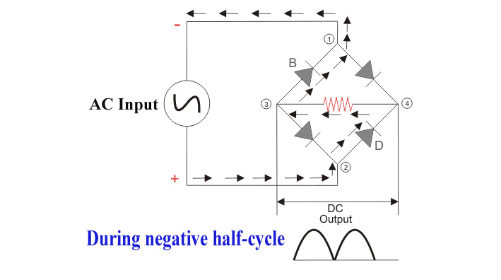 During the negative half-cycle, the conducting diodes change, but the bridge rectifier maintains unidirectional current through the load, converting both half-cycles of AC into pulsating DC.
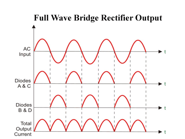
Output Waveform of Full Wave Rectifier
The output waveform of a full wave rectifier consists of a series of positive half sine waves. The important characteristics are:
- Both half-cycles of the AC input appear as positive output.
- Output frequency is twice the input frequency.
- Ripple content is lower compared to half-wave rectifier.
This makes the full wave rectifier more suitable for practical DC power supplies.
Advantages of Full Wave Rectifier
The full-wave rectifier offers several advantages over the half-wave rectifier:
- Higher Efficiency
Since both halves of the AC input are used, the rectification efficiency is significantly higher. - Lower Ripple Factor
The ripple content in the output DC is lower, resulting in smoother output voltage. - Better Transformer Utilization
The transformer is utilized more effectively as power is drawn during both half-cycles. - Higher Average Output Voltage
The average DC output voltage is higher compared to half-wave rectification. - Smaller Filter Size
Due to lower ripple, smaller and less expensive filters can be used. - Improved Power Quality
The output waveform is closer to pure DC, making it suitable for sensitive electronic circuits.
Disadvantages of Full Wave Rectifier
Despite its advantages, the full-wave rectifier has some limitations:
- Increased Circuit Complexity
Compared to half-wave rectifiers, the circuit is more complex. - Higher Cost
More diodes and sometimes a center-tapped transformer are required. - Diode Voltage Drop
In bridge rectifiers, two diodes conduct simultaneously, causing additional voltage drop. - Transformer Requirement
Center-tapped rectifiers require a special transformer, increasing size and cost. - Heat Dissipation
Multiple conducting diodes lead to higher power loss and heat generation.
Applications of Full Wave Rectifier
The full-wave rectifier is widely used in various electrical and electronic applications due to its high efficiency and better output quality.
1 Power Supply Units
Full-wave rectifiers are extensively used in DC power supplies for computers, televisions, radios, and communication equipment.
2 Battery Charging Circuits
They are used in battery chargers because they provide efficient and smoother DC output.
3 Industrial DC Drives
Full-wave rectifiers are used in DC motor drives to convert AC power into controlled DC.
4 Audio and Amplifier Circuits
They provide stable DC voltage required for audio amplifiers and signal processing circuits.
5 Electroplating and Welding
In electroplating and DC welding, full-wave rectifiers are used to obtain higher current and smoother DC output.
6 Medical Equipment
Medical devices such as X-ray machines and diagnostic instruments rely on full wave rectification.
7 UPS and Inverter Systems
Full-wave rectifiers are used in uninterruptible power supplies (UPS) and inverter systems to convert AC to DC.
Conclusion
The Full Wave Rectifier is a crucial circuit in power electronics that efficiently converts AC voltage into DC voltage by utilizing both half-cycles of the input waveform. Its improved efficiency, reduced ripple factor, and better output quality make it superior to half-wave rectifiers. Despite higher cost and complexity, its advantages outweigh the disadvantages in most practical applications. For this reason, full wave rectifiers are widely used in modern electronic power supply systems and industrial applications
Short Exam Answers (2–5 Marks)
- What is a Full Wave Rectifier?
Answer: A full wave rectifier is a circuit that converts the entire AC input waveform into pulsating DC by using both the positive and negative half-cycles of the AC supply.
- Why is a full wave rectifier more efficient than a half-wave rectifier?
Answer: Because a full wave rectifier utilizes both half-cycles of the AC input, it delivers higher DC output power and has greater efficiency than a half-wave rectifier.
- State any two advantages of a full wave rectifier.
Answer:
- Higher rectification efficiency.
- Lower ripple factor.
- State any two disadvantages of a full wave rectifier.
Answer:
- Circuit complexity is higher.
- Cost is higher due to additional diodes or special transformer.
- What is the ripple frequency of a full wave rectifier?
Answer: The ripple frequency of a full wave rectifier is twice the input AC supply frequency.
- Explain the working of a full wave rectifier during positive half-cycle.
Answer: During the positive half-cycle, the appropriate diode(s) become forward biased and conduct, allowing current to flow through the load in one direction, producing a positive output voltage.
- Explain the working of a full wave rectifier during negative half-cycle.
Answer: During the negative half-cycle, the remaining diode(s) conduct and reverse the polarity of the input, so current through the load flows in the same direction as during the positive half-cycle.
- Why is the ripple factor lower in a full wave rectifier?
Answer: Since both half-cycles of AC contribute to the output, the DC waveform is smoother, reducing the ripple content compared to a half-wave rectifier.
- Write any four applications of a full wave rectifier.
Answer:
- DC power supplies
- Battery charging circuits
- DC motor drives
- UPS systems
- Compare half-wave and full wave rectifier (any two points).
Answer:
- Half-wave rectifier uses only one half-cycle, while full wave rectifier uses both half-cycles.
- Full wave rectifier has higher efficiency and lower ripple factor.
- What is transformer utilization factor (TUF)?
Answer: Transformer utilization factor is the ratio of DC power delivered to the load to the AC power supplied by the transformer.
- Why are filters used with full wave rectifiers?
Answer: Filters are used to reduce ripple content and obtain smoother DC output voltage.
- Name the two types of full wave rectifiers.
Answer:
- Center-tapped full wave rectifier
- Bridge rectifier
Full Wave Rectifier – 30 MCQs with Answers
1. A full wave rectifier converts:
- AC to AC
B. DC to DC
C. AC to pulsating DC
D. DC to AC
✅ Answer: C
2. How many diodes are used in a bridge full wave rectifier?
- One
B. Two
C. Three
D. Four
✅ Answer: D
3. The output frequency of a full wave rectifier is:
- f
B. f/2
C. 2f
D. 4f
✅ Answer: C
4. The ripple factor of a full wave rectifier is approximately:
- 1.21
B. 0.812
C. 0.482
D. 0.212
✅ Answer: C
5. The maximum rectification efficiency of a full wave rectifier is:
A. 40.6%
B. 50%
C. 81.2%
D. 100%
✅ Answer: C
6. In a center-tapped full wave rectifier, how many diodes conduct at a time?
- Zero
B. One
C. Two
D. Four
✅ Answer: B
7. In a bridge rectifier, how many diodes conduct in each half-cycle?
- One
B. Two
C. Three
D. Four
✅ Answer: B
8. Which transformer is required for a center-tapped full wave rectifier?
- Step-up transformer
B. Step-down transformer
C. Center-tapped transformer
D. Auto-transformer
✅ Answer: C
9. Which rectifier does NOT require a center-tapped transformer?
- Half wave rectifier
B. Center-tapped full wave rectifier
C. Bridge rectifier
D. All rectifiers
✅ Answer: C
10. In a full wave rectifier, current through the load flows:
A. In both directions
B. In one direction only
C. Alternately forward and reverse
D. Stops during one half-cycle
✅ Answer: B
11. Transformer Utilization Factor (TUF) of a full wave rectifier is:
A. Lower than half wave rectifier
B. Equal to half wave rectifier
C. Higher than half wave rectifier
D. Zero
✅ Answer: C
12. The Peak Inverse Voltage (PIV) of each diode in a center-tapped full wave rectifier is:
A. Vm
B. Vm/2
C. 2Vm
D. 4Vm
✅ Answer: C
13. The Peak Inverse Voltage (PIV) of each diode in a bridge rectifier is:
A. Vm
B. Vm/2
C. 2Vm
D. 4Vm
✅ Answer: A
14. A full wave rectifier uses:
A. Only positive half-cycle
B. Only negative half-cycle
C. Both half-cycles
D. Alternate half-cycles only
✅ Answer: C
15. Compared to a half wave rectifier, a full wave rectifier has:
A. Lower DC output
B. Higher DC output
C. Same DC output
D. Zero DC output
✅ Answer: B
16. The main purpose of using a filter after a rectifier is to:
A. Increase AC voltage
B. Reduce ripple
C. Increase frequency
D. Increase efficiency
✅ Answer: B
17. The output of a full wave rectifier without a filter is:
A. Pure DC
B. Smooth DC
C. Pulsating DC
D. AC voltage
✅ Answer: C
18. Which property of a diode makes rectification possible?
A. High resistance
B. Unidirectional conduction
C. High capacitance
D. Inductance
✅ Answer: B
19. Full wave rectifiers are commonly used in:
A. Oscillators
B. Signal generators
C. DC power supplies
D. Modulators
✅ Answer: C
20. The ripple frequency of a full wave rectifier is:
A. f
B. f/2
C. 2f
D. 4f
✅ Answer: C
21. Which rectifier has better efficiency?
A. Half wave rectifier
B. Full wave rectifier
C. Both are equal
D. None
✅ Answer: B
22. In a full wave rectifier, the load current flows:
A. In both directions
B. In one direction only
C. In reverse direction
D. Stops for half-cycle
✅ Answer: B
23. Which rectifier provides better transformer utilization?
A. Half wave rectifier
B. Full wave rectifier
C. Clipper circuit
D. Clamper circuit
✅ Answer: B
24. In a bridge rectifier, voltage drop is higher because:
A. Transformer loss
B. One diode conducts
C. Two diodes conduct
D. Filter loss
✅ Answer: C
25. The DC component in the output of a full wave rectifier is:
A. Zero
B. Very small
C. Higher than half wave rectifier
D. Equal to AC component
✅ Answer: C
26. Half wave rectifier efficiency is approximately:
A. 40.6%
B. 50%
C. 81.2%
D. 90%
✅ Answer: A
27. Ripple is less in a full wave rectifier because:
A. Filter is used
B. Transformer is used
C. Both half-cycles are utilized
D. Diode resistance is high
✅ Answer: C
28. Full wave rectifiers are used in:
A. Battery chargers
B. UPS systems
C. DC motor drives
D. All of the above
✅ Answer: D
29. Which filter reduces ripple most effectively?
A. Capacitor filter
B. Inductor filter
C. LC filter
D. Transformer
✅ Answer: C
30. A full wave rectifier with filter is mainly used to obtain:
A. AC output
B. High-frequency signal
C. Smooth DC voltage
D. Square wave
✅ Answer: C