Electrical Engineering basic laws are –
What is of Ohm’s Law? What are the limitations of ohm’s law? Where are Applications of Ohm’s Law?
Ohm’s Law states that, the current (I) flowing through a conductor is directly proportional to the voltage (V) applied across the conductor and inversely proportional to the resistance (R) of the conductor.
Mathematically, it is expressed as: V=I×R
Where:
- V is the voltage (in volts, V),
- I is the current (in amperes, A),
- R is the resistance (in ohms, Ω).
Limitations of Ohm’s Law:
- Non-linearity: Does not apply to non-linear materials such as semiconductors, diodes, and transistors.
- Temperature effects: Resistance varies with temperature, making Ohm’s Law inaccurate under temperature variations.
- Frequency effects: In AC circuits, impedance (not resistance) must be used, as the relationship between current and voltage is frequency-dependent.
- High electric fields: At extremely high voltages or electric fields, Ohm’s Law may not apply due to breakdown or non-ohmic behavior.
- Superconductivity: In superconductors, where resistance is zero, Ohm’s Law does not apply.
- Complex materials: Materials with in homogeneities or varying resistance do not follow Ohm’s Law.
- Voltage-dependent resistance: Some materials have resistance that changes with voltage, causing deviations from the law.
Practical Applications of Ohm’s Law:
- Designing Electrical Circuits: Ohm’s Law helps engineers and electricians design circuits by calculating the required voltage, current, or resistance for safe operation.
- Troubleshooting: By measuring voltage and current, Ohm’s Law can be used to identify problems in circuits, such as faulty components or unexpected resistance.
- Power Calculations: Ohm’s Law also relates to electrical power. Power (P) can be calculated as: P = V×I = I2×R = V2 /R
Where P is the power (in watts).
Kirchhoff’s Law
Kirchhoff’s Law: Kirchhoff’s Laws are fundamental principles used to analyze electrical circuits. They are based on the principles of conservation of energy and charge. There are two main laws:
1. Kirchhoff’s Current Law (KCL):
Also known as the First Law or Node Law, it states that the total current entering a junction (or node) in an electrical circuit must equal the total current leaving the junction.
Mathematically:
∑in = ∑out
Where:
- Iin is the current flowing into the node.
- Iout is the current flowing out of the node.
This law is applied at each node (junction) in the circuit.
Example of KCL:
At a node, if three currents are entering the node, I1=2 A, I2=3 A, and I3=4, then the total current leaving the node must be: Iout= 2+3+4 =9 A
2. Kirchhoff’s Voltage Law (KVL):
Also known as the Second Law or Loop Law, it states that the sum of all electrical potential differences (voltages) around any closed loop in a circuit must equal zero. This is a consequence of the law of conservation of energy.
Mathematically:
∑V=0
Where:
- V is the voltage across each component in the loop.
- The sum includes both positive and negative voltages, depending on the direction of the loop and the polarity of the components.
Example of KVL:
Consider a simple loop with a 12V battery, a 3Ω resistor, and a 6Ω resistor:
Battery voltage−(Voltage drop across 3Ω+Voltage drop across 6Ω)=0
12V−(3I+6I)= 0
Where I is the current through the loop.
KVL is applied to loops in the circuit where all voltages are considered, including those from sources (like batteries) and resistive elements.
Application:
These laws are impotant for solving complex electrical circuits, where they allow for the calculation of unknown currents and voltages in a network of resistors, capacitors, and inductors.
Kirchhoff’s Laws are essential for analyzing and solving electrical circuits and are widely used in various fields, such as electronics, power distribution, and electrical engineering.
Coulomb’s Law:
Coulomb’s Law states that the electrostatic force between two point charges is directly proportional to the product of the magnitudes of the charges and inversely proportional to the square of the distance between them.
Mathematically, Coulomb’s Law is expressed as: F=ke⋅q1⋅q2 /r2
Where:
- F is the magnitude of the electrostatic force between the two charges.
- q1 and q2 are the magnitudes of the two point charges.
- r is the distance between the charges.
- k is the electrostatic constant (also called Coulomb’s constant), which is approximately 8.99×10⁹ N⋅m2/C2
Applications of Coulomb’s Law:
- Electrostatics: To calculate forces between charged objects in static electricity problems.
- Atomic and Molecular Physics: Coulomb’s law helps explain the interactions between electrons and nuclei in atoms.
- Electric Fields: Coulomb’s law is used to derive the electric field generated by point charges.
04. LENZ LAW
Lenz’s Law states that the direction of the induced electromotive force (emf) and the resulting current in a closed loop will always oppose the change in magnetic flux that caused it. This is a consequence of the law of conservation of energy and is expressed mathematically as part of Faraday’s Law of Induction.
Lenz law indicates the direction of induced current.
Formula:
Lenz’s Law is incorporated into Faraday’s Law of Induction, which states:
ε = − dΦB/dt
Where:
- ε is the induced electromotive force (emf).
- ΦB is the magnetic flux through the circuit.
- dΦB /dt is the rate of change of the magnetic flux.
- The negative sign is a direct representation of Lenz’s Law, indicating that the induced emf opposes the change in flux.
Examples of Lenz’s Law:
1. Moving Magnet and Coil:
When a magnet is moved towards a coil, the magnetic flux through the coil increases. According to Lenz’s Law, the induced current in the coil will generate a magnetic field that opposes the magnet’s motion (i.e., the magnetic field of the coil will try to repel the approaching magnet). If the magnet is moved away from the coil, the induced current will try to maintain the flux, generating a magnetic field that attracts the magnet.
2. Induction Cooking:
In induction cooktops, an alternating current is passed through a coil beneath the cooking surface, creating a changing magnetic field. This induces eddy currents in the cooking pot, which in turn generates heat. The direction of the induced current in the pot opposes the change in magnetic flux, leading to the generation of heat due to the resistance of the material.
3. Eddy Currents:
When a conductor moves through a magnetic field, it induces circulating currents (called eddy currents) within the conductor. Lenz’s Law dictates that these currents will create their own magnetic fields that oppose the motion of the conductor. This opposition leads to a force that resists the motion, a principle used in eddy current brakes (non-contact braking systems).
Applications of Lenz’s Law:
- Electric Generators: Lenz’s Law explains the opposition between the motion of the armature and the induced current in a generator.
- Transformers: It helps in understanding how transformers work by changing the magnetic flux to induce voltage in a secondary coil.
- Eddy Current Brakes: Used in non-contact braking systems, relying on the resistance induced by Lenz’s Law.
- Inductive Heating: In induction cookers and metal hardening processes, Lenz’s Law is used to create heat by opposing the change in magnetic flux.
05. FLEMING’S LEFT HAND RULE.
This rule helps to find the direction of the motion of the conductor placed in magnetic field with current flowing through it.
Fleming’s Left Hand Rule states that:
If a conductor is placed in magnetic field and current is flowing through it, then it will experience a force which is mutually perpendicular to the field and current.
If we stretch the fingers of left hand as shown in figure, then
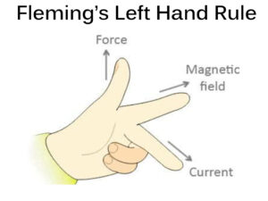
- Index finger will represent the direction of magnetic field.
- Middle finger shows the direction of current.
- Thumb represents the direction of force.
This principle is used in the working of DC MOTOR.
06. FLEMING’S RIGHT HAND RULE.
Fleming’s Right Hand Rule helps to find the direction of induced current in the conductor when a conductor moves in the magnetic field.
0
This rule is used in finding the direction of induced current in generator windings.
If we stretch the fingers of right hand as shown in figure, then
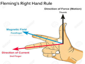
- Thumb represents the direction of motion.
- Index finger represents the direction of magnetic field.
- Middle finger represents the direction of induced current in the conductor.
07. FARADAY’S LAW OF ELECTROMAGNETIC INDUCTION.
Faraday’s Law of Electromagnetic Induction is a fundamental principle in electromagnetism that describes how a changing magnetic field can induce an electromotive force (emf) in a conductor.
Faraday’s First Law is part of the broader concept of electromagnetic induction and is often referred to in conjunction with Faraday’s Second Law.
Faraday’s First Law:
Faraday’s First Law of Electromagnetic Induction states that:
“The magnitude of the induced electromotive force (EMF) in a closed loop is directly proportional to the rate of change of the magnetic flux through the loop.”
Magnetic Flux: It is the product of the magnetic field strength (B) and the area (A) through which the field lines pass, and it is represented as ΦB=B×A×cos(θ)
Where θ is the angle between the magnetic field lines and the normal to the surface.
Induced EMF: According to Faraday’s Law, the induced EMF ε is related to the rate of change of magnetic flux through a loop:
Mathematical Expression:
The first law is expressed mathematically as: ε = − dΦB/dt
Where:
- ε is the induced electromotive force (emf) in the coil.
- ΦB is the magnetic flux through the loop.
- dΦB/dt represents the rate of change of magnetic flux.
- The negative sign represents the direction of the induced emf as explained by Lenz’s Law, which tells us that the induced current will oppose the change in magnetic flux.
Faraday’s First Law is the foundational principle behind electric generators, transformers, and many other devices that use electromagnetic induction.
Faraday’s Second Law:
Faraday’s Second Law of Electromagnetic Induction is a more specific statement about the induced electromotive force (EMF) and how it depends on the rate of change of the magnetic flux. It is mathematically expressed as:
“The magnitude of the induced EMF is directly proportional to the rate of change of the magnetic flux linkage.”
Mathematically:
Faraday’s Second Law is usually written as:
ε= − N dΦB/dt
Where:
- ε is the induced EMF,
- N is the number of turns in the coil (for a coil with multiple loops),
- ΦB is the magnetic flux through each loop,
- dΦB/dt is the rate of change of the magnetic flux through the loop.
Note:
- Faraday’s First Law explains that a change in magnetic flux induces an EMF, while Faraday’s Second Law gives the specific relationship between the induced EMF and the rate of change of flux.
- The Second Law quantifies the effect, showing that the induced EMF is directly proportional to how quickly the magnetic flux changes and how many turns are in the coil.
Pingback: Current Transformer (CT)'s type, Working principle & Phasor Diagram - EEE AtoZ