10 Key Questions about EEE Job Interview are bellow-
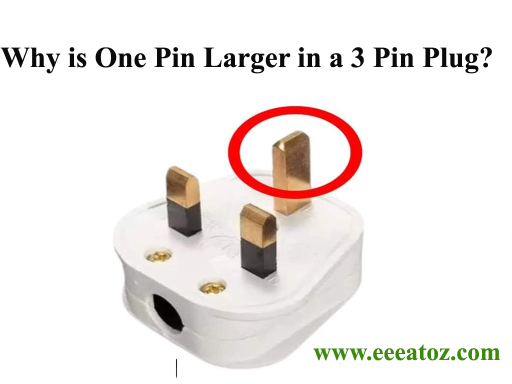
Why is One Pin Larger in a 3 Pin Plug?
Answer: The reason one pin in a 3-pin plug is larger is for safety, specifically related to the “earth” or “ground” connection.
Earth/Ground Pin:
- The larger pin is the earth or ground pin. Its primary function is to provide a safe path for electrical current to flow in the event of a fault.
- This prevents electrical shocks by diverting stray currents away from the appliance and the user.
Why Larger?
- Safety First: The larger size ensures that the earth pin is the first to make contact when the plug is inserted and the last to disconnect when it’s removed. This prioritizes the grounding connection.
- Preventing Incorrect Insertion: The size difference also prevents the plug from being inserted incorrectly. This ensures that the earth connection is always established properly.
- Essentially this design is made to make sure that the earth wire is connected before the live and neutral wires, and disconnected after the live and neutral wires. This is a very important safety feature.
In essence, the larger earth pin is a important safety feature designed to protect users from electrical hazards.
In a gas turbine plant, suddenly the work output is dropped. The rpm of turbine is the same but the exhaust temperature is higher. What is the reason behind this? Find a solution to overcome this.
Answer:
Possible Reasons:
Compressor Fouling or Damage:
- Fouling (buildup of dirt, dust, or other contaminants) on the compressor blades reduces the compressor’s efficiency. This leads to a lower mass flow rate of air, even at the same RPM.
- Damaged compressor blades can also reduce efficiency and mass flow.
- Reduced mass flow, with the same fuel input, will result in a higher exhaust gas temperature.
Turbine Fouling or Damage:
- Similar to the compressor, fouling or damage on the turbine blades reduces the turbine’s efficiency.
- This can result in less work output, even with the same amount of heat input.
- Also damage to the turbine sealing can cause gasses to bypass the turbine blades, therefore reducing efficiency.
Combustion Problems:
- Inefficient combustion can lead to a higher exhaust temperature. This could be caused by:
- Fuel injector problems.
- Variations in fuel composition.
- Air/fuel mixture imbalances.
- Inefficient combustion can lead to a higher exhaust temperature. This could be caused by:
Ambient Conditions:
- A significant increase in ambient temperature reduces the density of the inlet air, leading to a lower mass flow rate.
- This can have a similar effect to compressor fouling.
Internal Leaks:
- Leaks within the gas turbine system, allowing compressed air to escape before reaching the turbine, reducing the working fluid that drives the turbine.
Solutions:
Regular Cleaning and Maintenance:
- Regularly clean the compressor and turbine blades to prevent fouling.
- Conduct routine inspections to identify and repair any damage to the compressor or turbine.
Fuel System Inspection:
- Inspect and maintain the fuel injectors and fuel delivery system to ensure proper fuel atomization and combustion.
- Monitor fuel quality and composition.
Air Intake Filtration:
- Ensure the air intake filters are clean and functioning properly to prevent contaminants from entering the compressor.
Environmental Monitoring:
- Monitor ambient temperature and adjust turbine operation accordingly. Some gas turbine plants have inlet air cooling systems to prevent this.
Internal Inspection and Repair:
- Periodic inspections of internal seals and gas pathways, to insure that there are not any gas leaks.
Performance Monitoring:
- Continuously monitor the turbines performance with sensors, and software to detect degradations in performance as they occur.
In summary, a higher exhaust temperature with the same RPM but lower work output indicates a loss of efficiency, most likely due to a reduction in mass flow or inefficient combustion. Consistent maintenance and monitoring are crucial to preventing and addressing these issues.
3. Why is the Star-Delta connection used in motors?
Answer:
The Star-Delta connection is used to reduce the initial starting current of motors. Starting a motor directly in delta can result in a very high inrush current, which can damage equipment and cause voltage dips. In Star configuration, the motor operates at a reduced voltage, reducing the starting current to about 1/3 of the delta starting current. After the motor reaches a certain speed, it is switched to Delta to run at full voltage and power.
4. What happens if a motor is directly connected to the Delta configuration?
Answer:
If a motor is directly connected to Delta, it will experience a high starting current that can be up to 5 to 7 times the full load current. This can lead to electrical damage, voltage sag, and reduced lifespan of the motor and electrical equipment.
What is the difference between real power, apparent power, and reactive power?
Answer:
- Real Power (P): This is the actual power used to do useful work in the circuit, measured in watts (W).
- Apparent Power (S): This is the total power supplied to the circuit, both real and reactive power, measured in volt-amperes (VA).
- Reactive Power (Q): This power does not perform useful work but is necessary to maintain the voltage levels in the circuit. It is measured in volt-amperes reactive (VAR).
These three types of power are related by the following equation:
S = sqrt√{P^2 + Q^2}
The power factor is the ratio of real power (P) to apparent power (S).
- What do you mean ideal voltage source and ideal current source?
Answer:
1. Ideal Voltage Source
- An ideal voltage source is a source that can maintain a constant voltage across its terminals, regardless of the current drawn from it. It does not have any internal resistance or impedance.
- Key Characteristics:
- Constant Voltage: The voltage output remains fixed no matter how much current is drawn from it.
- Zero Internal Resistance: An ideal voltage source has no internal resistance or reactance.
- Unlimited Current: It can supply any amount of current without affecting the output voltage.
- Symbol: Represented by a circle with a “+” and “-” sign, indicating positive and negative terminals.
- Example: Theoretically, a battery with no internal resistance or an ideal power supply.
Ideal Voltage Source Formula:
Vout =Constant value
Regardless of the load current, the voltage across the terminals stays the same.
Ideal Current Source
- An ideal current source is a source that can provide a constant current, regardless of the voltage across its terminals. It has an infinite internal resistance or impedance.
- Key Characteristics:
- Constant Current: The current supplied by the source is fixed, regardless of the load or voltage across it.
- Infinite Internal Resistance: The current source has an infinite internal resistance, meaning it cannot allow any current change due to varying voltage.
- Variable Voltage: The voltage across an ideal current source adjusts itself to maintain the specified current, depending on the load.
- Symbol: Represented by a circle with an arrow indicating the direction of the current.
- Example: A theoretical current generator or an ideal current-controlled power supply.
Ideal Current Source Formula:
Iout =Constant value
The current remains the same, and the voltage varies depending on the load resistance.
Is ohm’s Law true for all conductors?
Answer: No, it is true only for metallic conductors provided physical conditions do not change.
Can we verify ohm’s law by using a filament lamp?
Answer: No, a filament lamp is a non-ohmic device. This means its resistance changes with temperature, making a direct, linear verification of Ohm’s law difficult.
Ohm’s Law:
- Ohm’s law states that the voltage (V) across a conductor is directly proportional to the current (I) flowing through it, provided the temperature remains constant. This is expressed as V = IR, where R is the resistance.
Filament Lamp Behavior
- A filament lamp, typically made from tungsten, does not follow Ohm’s Law in the strict sense. This is because the resistance of the filament changes with temperature. When the current flows through the filament, it heats up. The temperature increase causes the filament’s resistance to increase significantly. Therefore, the relationship between voltage and current is no longer linear.
The filament lamp does not strictly obey Ohm’s Law because its resistance is not constant. The relationship between voltage and current is non-linear due to the temperature dependence of the resistance
What is difference between over load and short circuit load?
Answer: An over load means that the circuit is carrying more than the rated current. A short circuit is said to occur if the circuit carries an exceedingly high current. In general, if the circuit carries more than 10 times the rated current, then short circuit should be suspected.
Can you measure the e.m.f of a cell with voltmeter?
Answer: Not accurately, it is because when voltmeter is connected across the cell, current starts flowing through it. This causes a voltage drop across the internal resistance of the cell. Consequently, the voltmeter will not indicate the e.m.f of the cell. Remember, e.m.f if a cell is the voltage across the open circuit terminals of the cell i.e, voltage across the terminals of the cell when it carries no current.