What is a Distance Relay?
A distance relay is a type of protective relay used primarily for the protection of high-voltage transmission lines. Unlike overcurrent relays, its operation depends on the electrical distance to a fault, which it determines by measuring the impedance (Z) between the relay location and the fault point.
Distance Relay Theory:
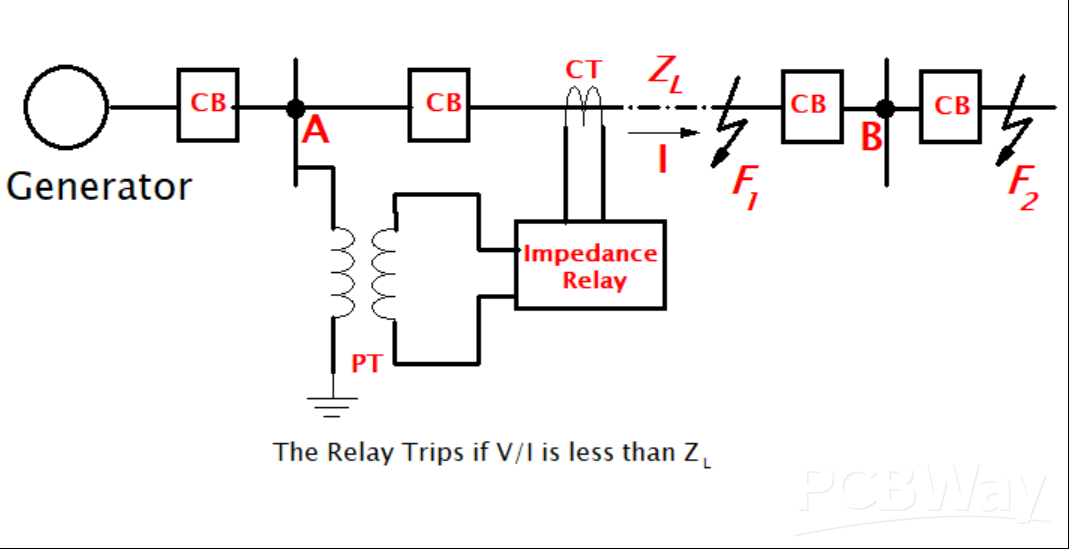
The fundamental principle relies on the relationship between impedance, voltage, and current, as defined by Ohm’s Law (V = I Z). The impedance of a transmission line is directly proportional to its length (distance). The relay continuously monitors the voltage (V) and current (I) on the line via potential transformers (PTs) and current transformers (CTs), respectively.
When a fault (like a short circuit) occurs on the transmission line-
- The current (I) increases
- The voltage (V) decreases at the point of the fault.
The relay calculates the impedance Zmeasured = V/I.
Working Principle
- Normal Condition: The line voltage is high and the current is normal. The measured impedance (Zmeasured) is greater than the relay’s predetermined set impedance ( Zset), and the relay remains inactive.
- Fault Condition: The voltage drops and the current rises, causing the measured impedance (Zmeasured) to drop drastically.
- Operation: If the measured impedance (Zmeasured) falls below the relay’s set impedance (Zset), the relay assumes a fault has occurred within its protected zone (distance) and generates a trip signal to the associated circuit breaker to isolate the faulty section.
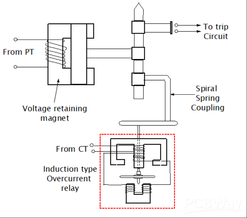
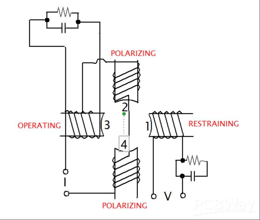
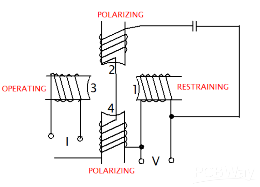
The relay utilizes two operating quantities:
- A deflecting torque (or operating torque) is typically produced by the current element.
- A restoring torque (or restraining torque) is produced by the voltage element.
The relay operates when the deflecting torque exceeds the restoring torque, which occurs when the V/I ratio (impedance) is low.
Types of Distance Relays
Distance relays are typically classified based on their operating characteristics when plotted on an R-X diagram (Resistance vs. Reactance plane):
1. Impedance Relay:
- Characteristic: A circle centered at the origin of the R-X plane.
- Operation: Responds to the magnitude of the impedance (Z|). It is non-directional, meaning it operates for faults in both forward and reverse directions, often requiring an additional directional element.
2. Reactance Relay:
- Characteristic: A straight line parallel to the Resistance (R) axis.
- Operation: Responds only to the reactance (X) component of the impedance. It is useful for protecting short lines where fault arc resistance can be significant. It is also non-directional and requires a separate directional element.
3. Mho Relay (Admittance Relay):
- Characteristic: A circle that passes through the origin of the R-X plane.
- Operation: Responds to the admittance (Y) and is inherently directional, making it highly preferred for long transmission lines.
4. Definite Distance Relays:
Definite Distance Relays are those that operate instantaneously (without intentional time delay) whenever the measured line impedance (Zmeasured) falls below a preset ohmic value (Zset), regardless of how far the fault is within that designated zone.
5. Time-Distance Relays:
Time-Distance Relays are designed to have an operating time that is proportional to the distance (or impedance) of the fault from the relay; a fault closer to the relay (lower Zmeasured) results in a faster trip, while a fault farther away (higher Zmeasured) is cleared with a time delay, allowing for simpler time coordination between relays.
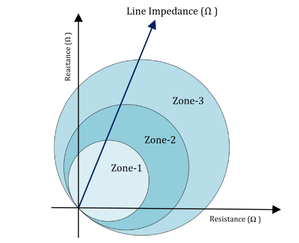
Distance protection schemes often use multiple zones (e.g., Zone 1, Zone 2 and Zone 3) with different time delays to provide both primary and backup protection, ensuring coordination.
Distance Relay Testing and Its Procedure
Testing a distance relay ensures its accuracy, speed, and selectivity are correctly aligned with the system settings and protection zones. The testing is typically done using specialized test equipment, such as a relay test set (e.g., an OMICRON CMC).
General Procedure (Secondary Injection Testing)
Preparation and Configuration:
- Connect the test set to the relay’s current transformer (CT) and potential transformer (PT) secondary inputs.
- Input the relay specifications and power system data (CT/PT ratios, line impedance, zone settings) into the test set software.
Pickup and Drop-out Tests:
- Verify the relay’s tripping threshold. For example, inject a high current and then slowly decrease the voltage until the relay trips, or vice-versa, to confirm the V/I ratio (Zset) is correct.
Zone Reach and Timing Tests (Impedance Measurements):
- This is the most critical step. Test points are defined on the R-X plane (in the impedance plane) for each protection zone.
- Trip/No-Trip Test: Inject voltage and current (as a complex impedance Z = R + jX) corresponding to points inside and outside each zone characteristic (Zone 1, Zone 2, etc.) to verify the relay trips for internal faults and doesn’t trip for external faults.
- Time Test: Measure the operating time for faults placed at various distances within the zones to confirm the intentional time delays (e.g., instantaneous for Zone 1, delayed for Zone 2).
Directional Test (for directional relays like Mho):
- Inject faults in both the forward and reverse directions to confirm the relay only operates for faults in the intended forward direction.
Ancillary Functions Test:
- Test other related functions like Power Swing Detection, Weak Infeed Logic, and Teleprotection schemes.
Distance Relay Characteristics
The operating characteristic of a distance relay is typically plotted on an R-X diagram (Resistance on the X-axis, Reactance on the Y-axis), where the impedance of the transmission line is represented as a straight line. The shape of the characteristic defines the region of operation (the protection zone). The main types are:
| Relay Type | R-X Characteristic Shape | Primary Feature/Application |
| Impedance Relay | A Circle centered at the origin. | Responds to the magnitude of impedance ($ |
| Reactance Relay | A Straight line parallel to the R-axis. | Responds to Reactance ($X$) only; less affected by fault resistance (arc resistance). Suitable for short lines. |
| Mho Relay | A Circle that passes through the origin. | Inherently directional and least affected by power swings. Preferred for long transmission lines. |
| Quadrilateral Relay | A four-sided polygon. | A more advanced characteristic providing a greater coverage for high fault resistances (like ground faults). |
Advantages
- Speed and Selectivity: Provides very high-speed protection and excellent selectivity, as its operation depends only on the distance (impedance) to the fault, regardless of the magnitude of the fault current.
- Independent of Source Impedance: Its reach is largely independent of changes in system generation or fault levels (unlike overcurrent relays).
- Layered Protection (Zoning): Allows for the division of the line into multiple protection zones (Zone 1, Zone 2, Zone 3) with progressively increasing time delays, offering precise primary protection and time-coordinated backup protection.
- Permanent Setting: Settings are based on the line’s fixed impedance and generally do not require readjustment for system changes.
- Directional Capability: Certain types (Mho, Quadrilateral) are inherently directional, preventing operation for faults behind the relay.
Disadvantages
- Accuracy Issues: The relay’s accuracy can be affected by fault arc resistance, power swings, variations in line impedance due to weather, and complex system configurations (e.g., parallel lines, series compensation).
- Underreach/Overreach: If settings are not precise, the relay may:
- Underreach: Fail to trip for a fault just outside its intended zone.
- Overreach: Trip for a fault beyond its intended zone (i.e., on an adjacent section).
- Cost and Complexity: More expensive and complex to apply and coordinate compared to simple overcurrent relays, requiring more detailed engineering analysis.
- Zero Voltage Faults: For very close-in faults (bolted faults), the voltage at the relay location can drop near zero, making it difficult for the relay to correctly determine the fault direction (often solved with “memory action” in modern relays).
Applications
Distance relays are essential components of modern power system protection schemes, primarily used for:
- Transmission Line Protection: Their main application is providing primary and backup protection for high-voltage (HV) and extra-high-voltage (EHV) overhead and underground transmission lines against all types of phase and ground faults.
- Backup Protection: They serve as reliable backup protection for other equipment like transformers, generators, and busbars in case their dedicated primary protection fails.
- Phase and Ground Faults: They are applied for protecting against line-to-ground, line-to-line, and three-phase
- Short and Long Lines: Different types are selected based on line length:
- Reactance Relays for short lines.
- Mho Relays for long lines.