What is DC Motor?
An electric motor that runs on direct current (DC) is known as a DC motor. It transforms electrical energy into mechanical energy. The mechanical energy is usually in the form of rotary motion, which can be used to drive fans, pumps, compressors, elevators, rolling mills, printing presses, traction systems, and many other applications.
Even though AC motors have gained more importance in modern industries due to their robustness and ease of operation, DC motors are still extensively used where speed control over a wide range and high starting torque are required.
Construction of a DC Motor
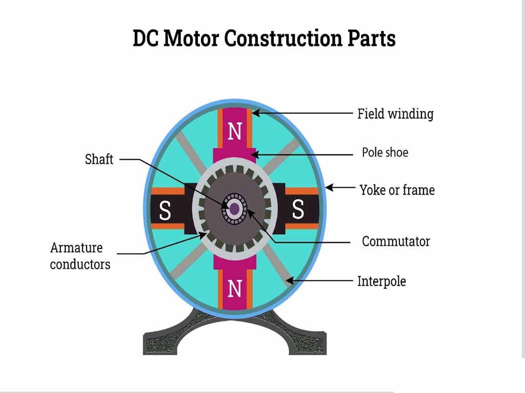
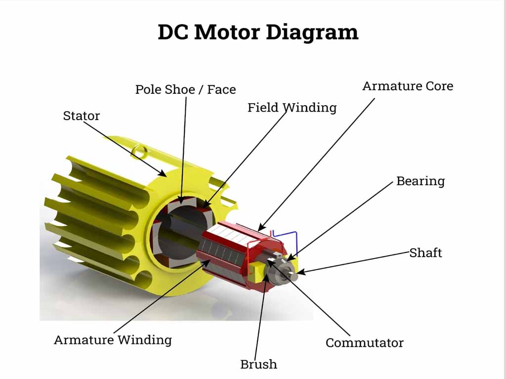
A DC motor is essentially similar in construction to a DC generator, except that the energy conversion process is reversed. The main parts of a DC motor can be classified as follows:
Stator: The Stationary Powerhouse
The stator is the stationary outer part of the motor. Its primary function is to provide a stable magnetic field. This magnetic field can be created in one of two ways: by using permanent magnets or by using electromagnets.
- Permanent Magnet Stator: In smaller DC motors, permanent magnets are often used to generate the magnetic field. These magnets have a fixed magnetic polarity and provide a constant magnetic flux. This design is simple, cost-effective, and efficient for low-power applications.
- Electromagnet Stator (Field Windings): In larger, more powerful DC motors, the magnetic field is generated by electromagnets. This is achieved by winding coils of wire, known as field windings or field coils, around a core made of a ferromagnetic material. When a direct current flows through these windings, a strong and controllable magnetic field is produced. The strength of this magnetic field can be varied by adjusting the current flowing through the field windings, offering a degree of control over the motor’s performance.
The main components of the stator are:
- Yoke (or Frame): The outer frame of the motor, typically made of cast iron or steel. It provides mechanical support for the other components and serves as a path for the magnetic flux produced by the field windings.
- Poles and Pole Shoes: Protruding from the yoke are the poles, around which the field windings are wound. The pole shoes are the expanded ends of the poles that face the rotor. Their curved shape helps to distribute the magnetic flux more uniformly in the air gap between the stator and the rotor.
- Field Windings: As mentioned, these are the coils of insulated copper wire wound around the poles. The current flowing through these windings creates the magnetic field.
Rotor (Armature): The Rotating Core
The rotor, also known as the armature, is the rotating part of the DC motor. It is cylindrical in shape and is mounted on a shaft that is free to rotate. The armature consists of several key components:
- Armature Core: This is a cylindrical core made of thin, laminated silicon steel sheets. The laminations are used to reduce energy losses due to eddy currents that are induced in the core as it rotates in the magnetic field. The core has slots on its outer periphery to house the armature windings.
- Armature Windings: These are coils of insulated copper wire placed in the slots of the armature core. When a direct current flows through these windings, they become electromagnets. The interaction between the magnetic field produced by the armature windings and the magnetic field of the stator creates the torque that causes the rotor to rotate.
- Commutator: The commutator is a crucial component that is unique to brushed DC motors. It is a segmented ring made of copper bars, with each segment insulated from the others. The ends of the armature coils are connected to these commutator segments. The commutator’s primary function is to reverse the direction of the current in the armature windings as the rotor turns. This reversal of current is essential to ensure that the torque on the armature is always in the same direction, resulting in continuous rotation.
- Brushes: The brushes are stationary carbon or graphite blocks that are held in contact with the rotating commutator segments by spring pressure. Their purpose is to conduct the direct current from the external power source to the armature windings via the commutator. As the commutator rotates, the brushes slide over its segments, ensuring a continuous electrical connection.
- Bearings & Shaft: The armature is mounted on a shaft supported by bearings for smooth rotation. The shaft transmits mechanical power to the load.
Working Principle of a DC Motor
The operation of a DC motor is based on a fundamental principle of electromagnetism known as the Lorentz force. This principle states that when a current-carrying conductor is placed in a magnetic field, it experiences a force. The direction of this force is determined by Fleming’s Left-Hand Rule.
Fleming’s Left-Hand Rule states that if you extend the forefinger, middle finger, and thumb of your left hand so that they are mutually perpendicular to each other, and if the forefinger represents the direction of the magnetic field and the middle finger represents the direction of the current in the conductor, then the thumb will indicate the direction of the force experienced by the conductor.
Here’s a step-by-step explanation of how a DC motor works:
- Establishing the Magnetic Field: When a DC voltage is applied to the field windings of the stator (in the case of an electromagnet stator), a steady magnetic field is established in the air gap between the stator poles. This magnetic field has a defined north and South Pole.
- Current Flow in the Armature: The DC supply is also connected to the armature windings through the brushes and the commutator. Current flows through the armature conductors.
- Force on the Armature Conductors: Now, we have current-carrying conductors (the armature windings) placed within a magnetic field (produced by the stator). According to the Lorentz force principle, each armature conductor experiences a force.
- Direction of Force and Torque Production: Let’s consider a simple two-pole DC motor. The conductors on one side of the armature (under the North Pole) will have current flowing in one direction, while the conductors on the opposite side (under the South Pole) will have current flowing in the opposite direction. According to Fleming’s Left-Hand Rule, the force on the conductors under the North Pole will be in one direction (e.g., upwards), and the force on the conductors under the South Pole will be in the opposite direction (e.g., downwards). These two forces, acting on opposite sides of the armature, create a turning effect or torque, causing the armature to rotate.
- The Role of the Commutator: As the armature rotates, the commutator segments also rotate and slide under the stationary brushes. After half a rotation (180 degrees), the commutator segments connected to a particular armature coil move to the position of the other brush. This action reverses the direction of the current flowing through that armature coil.
- Continuous Rotation: The reversal of current in the armature coils at the precise moment they pass the neutral axis (the point where the magnetic field is weakest) ensures that the torque on the armature is always in the same direction. The conductors that were previously under the North Pole and experiencing an upward force now come under the South Pole, and due to the current reversal, they now experience a downward force. Similarly, the conductors that were under the South Pole now experience an upward force. This continuous, unidirectional torque results in the continuous rotation of the armature.
In essence, the commutator and brushes act as a mechanical switch, constantly reversing the current in the armature windings to maintain a continuous rotational force.
Types of DC Motors
DC motors can be broadly classified based on how their field windings are connected to the armature. This connection arrangement significantly influences the motor’s speed and torque characteristics. The main types are:
DC Series Motor
In a DC series motor, the field winding is connected in series with the armature winding. This means that the entire armature current flows through the field winding.
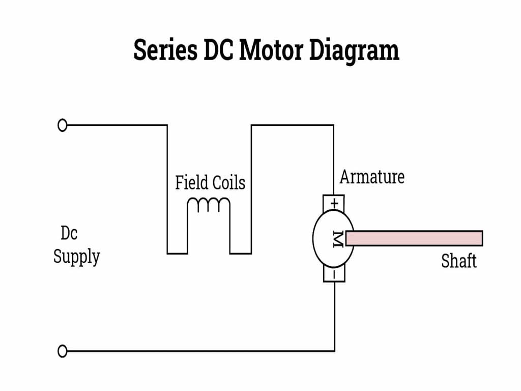
- Construction: The field winding is made of a few turns of thick wire, as it has to carry the full armature current.
- Characteristics:
- High Starting Torque: At starting, the armature current is very high, which also means the field current is high. Since torque is proportional to the product of armature current and field flux, the starting torque of a series motor is very high. This makes it ideal for applications that require a large initial turning force, such as electric trains, cranes, and hoists.
- Variable Speed: The speed of a series motor is highly dependent on the load. At no-load or light loads, the armature current is small, resulting in a weak magnetic field and dangerously high speeds. Therefore, a series motor should never be started without a load.
- Torque-Speed Relationship: The torque is inversely proportional to the square of the speed.
DC Shunt Motor
In a DC shunt motor, the field winding is connected in parallel (or shunt) with the armature winding. The field winding is connected across the same DC supply as the armature.
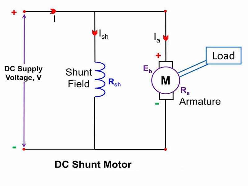
- Construction: The field winding consists of many turns of fine wire, giving it a high resistance. This is because it is connected in parallel with the low-resistance armature, and only a small portion of the total supply current should flow through the field winding.
- Characteristics:
- Constant Speed: A shunt motor is considered a constant speed motor. Its speed remains relatively constant from no-load to full-load. This is because the field current, and therefore the magnetic flux, is nearly constant as it is directly connected to the supply voltage.
- Low Starting Torque: The starting torque of a shunt motor is lower than that of a series motor.
- Applications: Due to their constant speed characteristics, shunt motors are used in applications where a constant speed is required, such as lathes, drills, and fans.
DC Compound Motor
A DC compound motor has both a series field winding and a shunt field winding. There are two subtypes based on how the windings are connected:
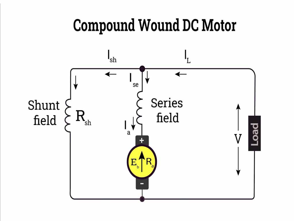
- Cumulative Compound Motor: In this type, the magnetic flux produced by the series field winding aids the magnetic flux produced by theshunt field winding. This motor combines the characteristics of both series and shunt motors. It has a higher starting torque than a shunt motor and better speed regulation than a series motor.
- Differential Compound Motor: Here, the magnetic flux of the series field winding opposes the magnetic flux of the shunt field winding. This type of motor is rarely used because as the load increases, the series field flux increases, weakening the total flux and causing the speed to rise. This can lead to instability.
Compound motors can also be classified as long shunt or short shunt depending on whether the shunt field is connected across both the armature and the series field (long shunt) or only across the armature (short shunt).
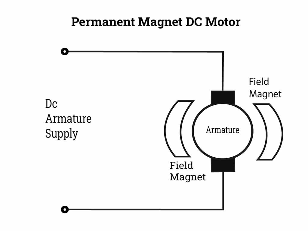
Permanent Magnet DC Motor
- Field is provided by permanent magnets instead of field winding.
- Compact, efficient, used in small devices like toys, wipers and robotics.
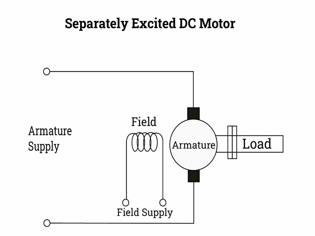
Separately Excited DC Motor
- Field winding powered by an independent DC source.
- Allows independent control of flux and armature current.
- Used in laboratories, testing, and precision applications.
Advantages and Disadvantages of DC Motors
DC motors offer a range of benefits but also have some drawbacks that need to be considered for specific applications.
Advantages
- High Starting Torque: DC series motors, in particular, provide excellent starting torque, making them suitable for heavy-duty applications.
- Excellent Speed Control: The speed of a DC motor can be easily and precisely controlled over a wide range by varying the armature voltage or the field current. This makes them ideal for variable speed applications.
- Simple Control: The control circuitry for DC motors is relatively simple and less expensive compared to that for AC motors.
- Good Transient Response: DC motors can respond quickly to changes in load and command signals.
Disadvantages
- Presence of Brushes and Commutator: The brushes and commutator are the most significant disadvantages of brushed DC motors. They are subject to wear and tear, requiring regular maintenance and replacement. They also produce sparks, which can be a fire hazard in certain environments and a source of electromagnetic interference.
- Higher Cost: The construction of a DC motor, especially the commutator, is more complex than that of an AC motor, leading to a higher manufacturing cost.
- Limited Lifespan of Brushes: The continuous friction between the brushes and the commutator limits the lifespan of the brushes.
- Audible and Electrical Noise: The sparking at the commutator can generate both audible and electrical noise.
It’s important to note that the development of brushless DC (BLDC) motors has overcome many of these disadvantages. BLDC motors use electronic commutation instead of mechanical brushes and a commutator, resulting in higher efficiency, longer lifespan, and lower maintenance.
Back EMF or Counter EMF of a DC Motor
When the armature of a DC motor rotates in the magnetic field produced by the stator, the armature conductors cut the magnetic flux lines. According to Faraday’s law of electromagnetic induction, an electromotive force (EMF) is induced in these conductors. This induced EMF always opposes the applied voltage (Lenz’s law) and is called Back EMF (Eb) or Counter EMF
The direction of this back EMF, as determined by Lenz’s law, is such that it opposes the cause that produces it. In this case, the cause is the supply voltage that is driving the motor. Therefore, the back EMF acts in opposition to the applied voltage.
Significance of Back EMF or Counter EMF
The concept of back EMF is of paramount importance in the operation and performance of a DC motor. It plays a crucial role in several aspects:
Self-Regulation of Armature Current
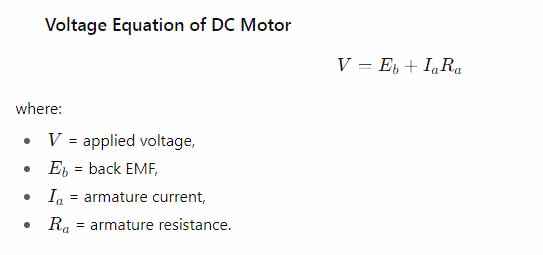
The back EMF acts as a self-regulating mechanism for the armature current. The net voltage across the armature is the difference between the applied voltage (V) and the back EMF (Eb). Therefore, the armature current (Ia) is given by:
Ia = RaV − Eb
Where Ra is the armature resistance.
Let’s consider what happens when the motor is started and when the load changes:
- At Starting: When the motor is just starting, the armature is stationary, so the speed (N) is zero. Consequently, the back EMF (Eb) is also zero. At this instant, the armature current is very high and is limited only by the small armature resistance:
Ia (start)=RaV
This high starting current can be several times the full-load current and can damage the motor if not controlled. This is why starters are used with DC motors to limit the initial current.
- As the Motor Speeds Up: As the motor gains speed, the back EMF increases. This increase in Eb reduces the net voltage across the armature (V−Eb), and consequently, the armature current (Ia) decreases. The motor will eventually reach a steady speed where the torque produced by the motor is equal to the load torque.
- Under Load: Now, suppose the load on the motor is increased. This will cause the motor to slow down slightly. The decrease in speed will lead to a decrease in the back EMF. A lower Eb will result in a larger net voltage across the armature, causing the armature current to increase. The increased armature current will produce more torque to meet the increased load demand.
- When Load Decreases: Conversely, if the load on the motor is decreased, the motor will speed up. The increase in speed will cause the back EMF to increase. This will reduce the net voltage and the armature current. The motor will draw less current from the supply, corresponding to the reduced load.
Therefore, the back EMF automatically adjusts the armature current to match the load on the motor. It is the reason why a DC motor draws more current when it is heavily loaded and less current when it is lightly loaded.
Conversion of Electrical Energy to Mechanical Energy
The back EMF is also a measure of the electrical energy that is being converted into mechanical energy. The power developed by the armature (Pm) is given by:
Pm = Eb×Ia
This equation shows that the mechanical power developed by the motor is directly proportional to the back EMF. The higher the back EMF, the more electrical power is being converted into useful mechanical work.
The total electrical power supplied to the armature (Pin) is:
Pin = V×Ia
This input power is divided into two parts:
- Mechanical Power Developed: EbIa
- Power Loss in Armature Resistance (Copper Loss): Ia2Ra
So, VIa = EbIa + Ia2Ra
This relationship highlights that the back EMF is the part of the applied voltage that is responsible for producing the mechanical output. The remaining voltage drop (IaRa) is due to the armature resistance and represents a power loss in the form of heat. For a motor to be efficient, the back EMF should be as close to the applied voltage as possible, which means the armature resistance should be low.
Protection of the Motor
The self-regulating nature of the back EMF helps to protect the motor from drawing excessive current under normal operating conditions. As explained earlier, if the load increases, the motor slows down, the back EMF decreases, and the armature current increases to provide the required torque. This automatic adjustment prevents the motor from stalling unless the load is excessively high.
Speed Regulation
The back EMF plays a important role in the speed regulation of a DC motor. Speed regulation is a measure of the change in speed of a motor from no-load to full-load. A motor with good speed regulation maintains a relatively constant speed over a wide range of loads. In a DC shunt motor, the back EMF is the primary factor that contributes to its excellent speed regulation.
In conclusion, the DC motor, with its rich history and diverse applications, remains a cornerstone of electrical engineering. Its elegant operating principle, based on the fundamental laws of electromagnetism, allows for the efficient conversion of electrical energy into mechanical motion. While the presence of brushes and a commutator in traditional DC motors presents some challenges, the advent of brushless technology has opened up new frontiers.
The concept of back EMF is not just a theoretical curiosity; it is the very essence of the DC motor’s self-regulating and energy-converting capabilities. A thorough understanding of its construction, working principles, various types, and the profound significance of back EMF is essential for anyone working with or designing systems that rely on the power and precision of DC motors.
This detailed exploration provides a comprehensive overview of the DC motor, from its basic components to the intricate interplay of magnetic fields and electrical currents that bring it to life.
Key Concept about Back e.m.f:
- Self-regulating action: Back EMF automatically adjusts armature current with load.
- Starting condition: At start, speed = 0, so (Eb = 0). Hence large current flows, requiring starters.
- Speed control: Since (Eb proportion to N), controlling (Eb) allows speed control.
- Efficiency: Proper balance between input voltage and back EMF ensures efficient energy conversion.
- Safety: Protects motor from over speeding and overloading.
Applications of DC Motors
- Electric traction (railways, trams, trolleys).
- Steel rolling mills, paper mills.
- Elevators, cranes, hoists.
- Electric vehicles.
- Small appliances (PMDC motors).
- Robotics and automation.