What is the Corona Effect in Transmission Lines?
The corona effect is the ionization of the air around a high-voltage conductor. When the electric field strength around the conductor exceeds a critical limit (~30 kV/cm for air), the surrounding air becomes ionized, causing:
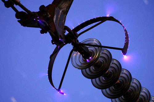
- A faint bluish glow
- Hissing noise
- Ozone production
- Power loss due to ionized air conducting current
What is Corona Discharge?
Corona discharge is the partial breakdown of air due to high voltage, where current flows through ionized air around conductors but not a full arc. It occurs in areas of high electric stress, like sharp edges, damaged insulation, or uneven conductor surfaces.
Advantages of Corona Effect
- Virtual Increase in Conductor Diameter: The ionized air around the conductor acts like an extension of the conductor, virtually increasing its diameter. This can help to reduce the maximum potential gradient on the conductor surface, reducing the probability of flashover.
- Useful in ozone generation and electrostatic precipitators
- Surge Protection: Corona can help dissipate the energy from voltage surges caused by lightning or switching operations.
- Helps detect insulation defects early (diagnostic tool)
Disadvantages of Corona Effect
Power Loss (Corona Loss): This is the most significant disadvantage. The ionization of air consumes energy, leading to power dissipation. This “corona loss” reduces the efficiency of the transmission line.
Audible Noise: The ionization process creates a characteristic hissing or crackling sound, which can be an annoyance, especially near populated areas.
Radio and Television Interference: The rapid ionization and de-ionization processes generate electromagnetic disturbances that can interfere with radio and television signals.
Ozone Production: Corona discharge produces ozone (O3) gas from the oxygen (O2) in the air. Ozone is corrosive and can react with the conductor material over time, leading to corrosion and degradation of the conductor and nearby insulation.
Harmonic Currents: The current drawn by the line due to corona is non-sinusoidal, which can introduce harmonics into the power system.
Insulation Damage: The long-term effects of ozone and localized heating can lead to the degradation and eventual breakdown of insulator materials.
Factors Affecting Corona Discharge
The magnitude and occurrence of corona discharge are influenced by several factors:
- Supply Voltage: Corona discharge is highly dependent on the electric field intensity, which is directly related to the applied voltage. Higher voltages lead to a more pronounced corona effect.
- Conductor Surface Condition: As mentioned, rough, dirty, or irregular surfaces (due to dust, dirt, scratches, or even raindrops/snow) create concentrated electric fields, lowering the disruptive voltage and increasing corona.
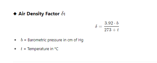
- Air Density Factor: Corona loss is inversely proportional to the air density factor. Lower air density (e.g., at higher altitudes or higher temperatures) reduces the dielectric strength of the air, making corona more likely and increasing losses.
- Spacing between Conductors: Smaller spacing between conductors increases the electric field strength, promoting corona.
- Conductor Size (Diameter): Smaller conductor diameters result in higher electric field intensities at the surface, thus increasing corona.
- Atmospheric Conditions: Humidity, fog, rain, and snow significantly increase corona loss due to the presence of water particles that provide additional paths for ionization.
Table: Factors Affecting Corona Discharge
| Factor | Effect |
| Voltage level | Higher voltage → More corona |
| Conductor radius | Larger radius → Less corona (reduces electric field strength) |
| Spacing between conductors | More spacing → Less corona |
| Surface condition | Rough/dirty surface → More corona |
| Air density (altitude) | Lower density → More corona |
| Weather | Humidity, rain, fog → Increase corona |
How Corona Effect is reduced?
- Increasing conductor diameter and using bundled conductors.
- Increasing the spacing between conductors.
- Using smooth conductors with polished surfaces.
- Designing lines to operate below the critical disruptive voltage as much as possible.
- Using corona rings on high-voltage equipment to smooth out electric field gradients at sharp points.
Important Parameters in Corona Analysis
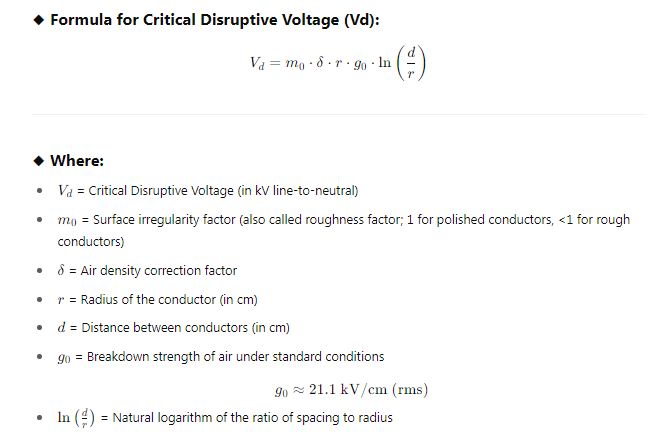
Critical Disruptive Voltage ():
This is the minimum phase-neutral voltage at which corona just begins to occur. It’s the voltage at which the potential gradient at the conductor surface reaches the dielectric strength of air.
Note:
- The formula gives phase voltage. Multiply by √3 to convert to line voltage (for 3-phase systems).
- If corona inception voltage (visual corona) is needed, a modified formula with visual critical voltage and empirical constants is used.
- All units must be consistent. If g0 is in kV/cm and r and d are in cm, Vc will be in kV.
- This formula calculates the phase-neutral voltage at which corona starts.
- The formula assumes parallel conductors and an infinitely long line, which is a simplification for practical transmission lines.
- The “ln” denotes the natural logarithm.
Visual Critical Voltage ():
This is the minimum phase-neutral voltage at which a visible glow (the actual “corona”) appears all along the line conductors. It’s typically higher than the critical disruptive voltage, as some ionization can occur before the glow becomes noticeable.
While corona discharge begins at the Critical Disruptive Voltage (Vc), it’s not immediately visible. A slightly higher voltage is required for sufficient ionization and excitation of air molecules to produce the characteristic faint violet glow. This is because the production of light from a discharge is due to the excitation of electrons and their subsequent emission of excess energy as photons, which requires a slightly higher energy level than just initial ionization.
The formula for Visual Critical Voltage is also an empirical formula, often given as a modification of the Critical Disruptive Voltage formula:
Where:
- Vv: Visual critical voltage in kV (RMS) per phase.
- mv: Visual irregularity factor. This factor is similar to for disruptive voltage but is specifically for the visual corona.
- For polished, smooth conductors: ≈1
- For rough or dirty conductors: is generally lower, around 0.72 to 0.82 for local corona on stranded conductors, and up to 0.82 for general corona.
- g0: Dielectric strength of air at standard temperature and pressure ().
- δ: Air density correction factor (same as for ).
- r: Radius of the conductor in cm.
- d: Spacing between the centers of the conductors in cm.
- ln: Natural logarithm.
The formula for Visual Critical Voltage is also an empirical formula, often given as a modification of the Critical Disruptive Voltage formula:
Vv =mvg0δr(1+δr0.3)ln(rd) kV/phase (RMS)
Where:
- Vv: Visual critical voltage in kV (RMS) per phase.
- mv: Visual irregularity factor. This factor is similar to m0 for disruptive voltage but is specifically for the visual corona.
- For polished, smooth conductors: mv ≈1
- For rough or dirty conductors: mv is generally lower, around 0.72 to 0.82 for local corona on stranded conductors, and up to 0.82 for general corona.
- g0: Dielectric strength of air at standard temperature and pressure (21.1 kV/cm (RMS)).
- δ: Air density correction factor (same as for Vc).
- r: Radius of the conductor in cm.
- d: Spacing between the centers of the conductors in cm.
- ln: Natural logarithm.
Key Notes:
- Vv >Vc: The visual critical voltage is always greater than the critical disruptive voltage. This means that corona discharge starts (and power loss begins) before the glow is actually seen.
- The term (1+ (0.3 / √δr) in the formula accounts for the additional energy required for the corona to become visible. This term depends on the air density and the conductor radius, indicating that larger conductors and denser air conditions require a slightly higher voltage for the glow to appear.
Power Loss Due to Corona (Corona Loss):
This refers to the energy dissipated in the system due to the ionization of air. It’s an undesirable power loss that reduces the efficiency of the transmission line. Various empirical formulas (like Peek’s formula) are used to estimate corona loss, which depends on factors such as voltage, frequency, conductor size, spacing, and atmospheric conditions.
How Engineers Overcome it?
Engineers employ several strategies to mitigate the corona effect and its undesirable consequences:
- Increasing Conductor Diameter: A larger conductor diameter reduces the electric field intensity at the surface for a given voltage. This is why ACSR (Aluminum Conductor Steel Reinforced) conductors with larger cross-sectional areas are commonly used in high-voltage lines.
- Increasing Spacing Between Conductors: By increasing the distance between conductors, the electric field intensity between them is reduced, thereby raising the voltage at which corona occurs. However, there’s a practical limit to this due to the increased cost of supporting structures.
- Using Bundled Conductors: Instead of a single large conductor, multiple smaller conductors are grouped together to form a “bundled” conductor. This effectively increases the overall equivalent diameter of the conductor, distributing the electric field over a larger surface area and significantly reducing the potential gradient at the surface.
- Maintaining Smooth Conductor Surfaces: Roughness, nicks, scratches, or even accumulation of dust, dirt, or water droplets on the conductor surface can create localized points of high electric field concentration, increasing the likelihood of corona. Engineers strive to use smooth conductors and design them to minimize surface irregularities.
- Corona Rings: These are toroidal (donut-shaped) metallic rings used on high-voltage equipment, especially at terminals or irregular hardware pieces (like insulator strings). They are electrically connected to the high-voltage conductor and designed to distribute the electric field gradient, lowering its maximum values below the corona threshold and preventing discharge at sharp points.
What is Corona Ring in the Transmission Line?
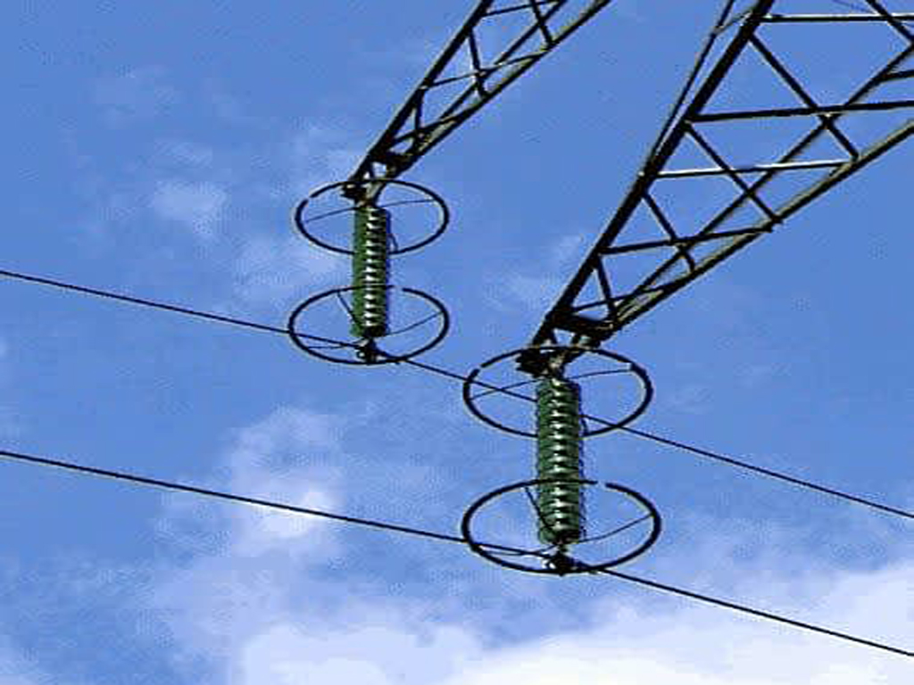
A corona ring (also known as an anti-corona ring) is a toroidal (ring-shaped) metallic device attached to high-voltage equipment, such as insulators or bushings, in transmission lines. Its primary purpose is to distribute the electric field gradient more uniformly around the point where it’s attached. By effectively increasing the radius of curvature at sharp points or terminals, the corona ring lowers the maximum electric field intensity below the critical value required for corona discharge, thereby preventing or significantly reducing corona formation and its associated problems like power loss and equipment degradation. They are typically used on very high voltage lines (e.g., above ).