Alternator
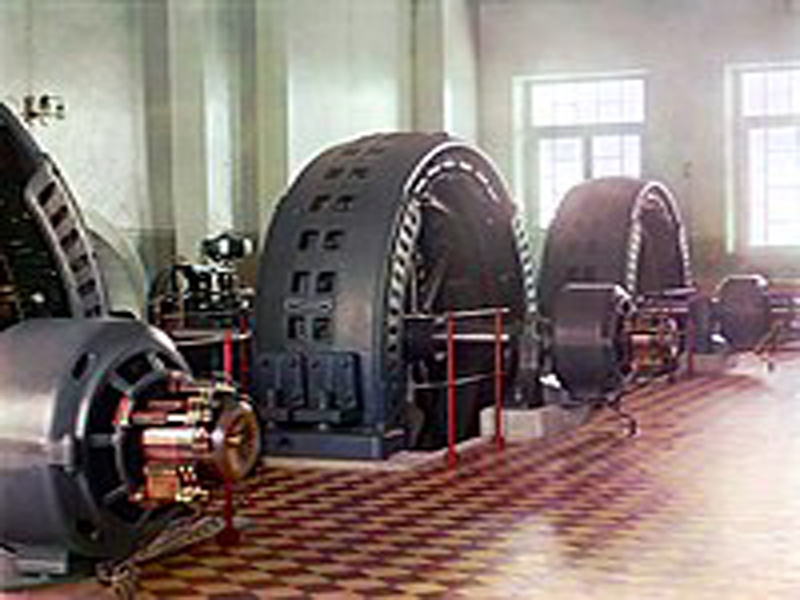
An alternator , more commonly known as a synchronous generator, is a vital electrical machine that converts mechanical energy into alternating current (AC) electrical energy. Its defining characteristic is that the rotor turns at a constant speed, known as synchronous speed, which is directly related to the frequency of the generated AC power. These generators are the backbone of power generation stations worldwide.
A 3-phase alternator is an electrical generator that converts mechanical energy into three-phase alternating current (AC) electrical energy.
Construction of a 3-Phase Alternator
A 3-phase alternator is comprised of two primary components: the stator and the rotor.
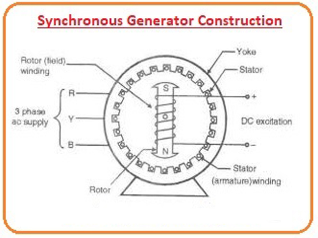
- Stator: This is the stationary part of the alternator and houses the armature winding. The stator core is constructed from high-grade silicon steel laminations to minimize energy losses. Slots are cut into the inner periphery of the core to hold the three-phase armature winding. This winding is where the voltage is induced.
- Rotor: The rotor is the rotating component and produces the magnetic field. There are two main types of rotor construction:
- Salient Pole Rotor: These rotors have poles that project outwards from the rotor core. They are typically used in low to medium-speed alternators, such as those driven by water turbines in hydroelectric plants.
- Cylindrical Rotor: These rotors have a smooth cylindrical shape with slots for the field winding. They are used in high-speed alternators, like those driven by steam turbines in thermal power plants, due to their mechanical robustness.
The field winding on the rotor is energized by a DC supply, often from a small DC generator called an exciter, which is mounted on the same shaft.
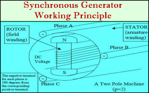
Working Principle of a 3-Phase Alternator
The operation of a 3-phase alternator is based on Faraday’s Law of Electromagnetic Induction. This law states that an electromotive force (EMF), or voltage, is induced in a conductor when it is subjected to a changing magnetic field.
Here’s a step-by-step breakdown of the working principle:
- Creating a Magnetic Field: A direct current (DC) is supplied to the field winding on the rotor. This creates a magnetic field with distinct north and south poles.
- Rotation: A prime mover, such as a turbine, rotates the rotor. As the rotor turns, the magnetic field it produces also rotates.
- Inducing Voltage: This rotating magnetic field cuts through the stationary armature conductors in the stator. According to Faraday’s law, this relative motion between the magnetic field and the conductors induces an alternating EMF in the stator windings.
- Three-Phase Output: The stator has three separate windings that are physically displaced by 120 degrees from each other. As the rotor’s magnetic field sweeps past these windings, it induces three separate alternating voltages. These voltages are of the same magnitude and frequency but are out of phase with each other by 120 electrical degrees, resulting in a three-phase power output.
The frequency of the generated AC voltage is directly proportional to the speed of the rotor and the number of poles on the rotor.
🔹 1. Salient Pole Rotor (Projecting Pole Type)
Construction
- Poles are large, projecting (salient) and fixed on a laminated steel rotor core.
- Poles are made of laminated steel to reduce eddy current losses.
- Each pole is wound with a field winding, excited by DC through slip rings.
- The pole shoes are spread to reduce the gap and produce a nearly sinusoidal flux distribution.
Features
- Large diameter, short axial length (disc-shaped).
- Used for low-speed machines (125 – 400 rpm).
- Requires a large number of poles to get standard frequency at low speed.
- Better cooling due to more surface area.
- Non-uniform air gap (minimum under poles, maximum between poles).
Applications
- Hydroelectric power plants (since water turbines run at low speed).
- Typically used in alternators up to 100 MVA.
🔹 2. Cylindrical Rotor (Non-Salient or Smooth Rotor)
Construction
- Rotor is solid cylindrical steel forging, with slots cut along the length.
- Field windings are embedded in these slots and held by wedges.
- Surface is smooth → nearly uniform air gap.
- Only two or four poles are used (sometimes up to 6).
Features
- Small diameter, long axial length (drum-shaped).
- Designed for high-speed operation (1500 – 3000 rpm).
- Rotational stresses are uniformly distributed.
- Produces sinusoidal flux due to uniform air gap.
- Limited cooling surface area, so uses forced cooling (hydrogen or air).
Applications
- Steam turbine-driven alternators (Turbo-generators).
- Used in very large power plants (hundreds of MVA capacity).
✅Summary:
- Salient Pole → Low-speed, hydro plants.
- Cylindrical Rotor → High-speed, steam/turbo alternators.
Advantages and Disadvantages of a 3-Phase Alternator
Advantages:
- Higher Power Output: For a given size, a 3-phase alternator can produce a significantly higher power output compared to a single-phase alternator.
- Constant Power Delivery: A 3-phase system delivers constant power to the load, resulting in smoother operation of machinery.
- More Economical: The transmission of three-phase power requires less conductor material than single-phase power for the same amount of power transfer.
- Self-Starting Motors: Three-phase induction motors are self-starting, which simplifies their design and operation.
- Higher Efficiency: Three-phase machines generally have a higher efficiency than single-phase machines of the same rating.
Disadvantages:
- Higher Insulation Cost: The insulation required for three-phase windings can be more complex and expensive.
- Increased Complexity: The overall system, including the generator and associated equipment, is more complex than a single-phase system.
- Higher Repair Costs: The cost of repairing a three-phase alternator is typically higher than that of a single-phase machine.
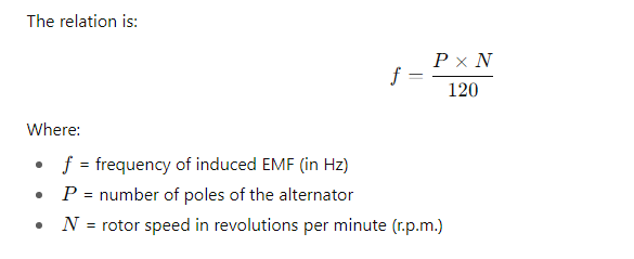
Frequency of induced E.M.F of 3 phase alternator:
The frequency of induced EMF in a 3-phase alternator depends on the speed of rotation of the rotor and the number of poles on the alternator.
✅ Explanation:
- When the rotor rotates, its magnetic poles sweep past the stator conductors.
- Each pair of poles produces one electrical cycle per revolution.
- Thus, more poles or higher speed → higher frequency.
Why the factor 120 comes in the formula?
Step 1: Rotor speed conversion
- Speed N is given in revolutions per minute (r.p.m.).
- But frequency f is in cycles per second (Hz).
- To convert minutes → seconds, divide by 60:
Revolutions per second (r.p.s.) = N / 60
Step 2: Electrical cycles per revolution
- For a rotor with P poles, there are P/2 pole-pairs.
- Each pole-pair produces 1 electrical cycle per revolution.
- So, electrical cycles per revolution = P/2
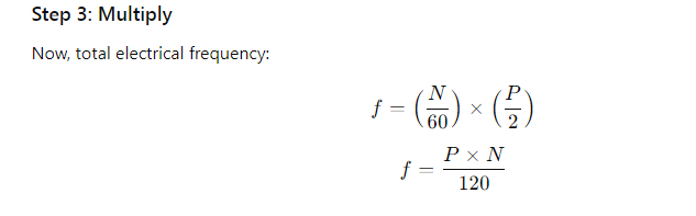
✅ So the 120 = 60 × 2 comes from:
- 60 → converting minutes to seconds.
- 2 → because one electrical cycle requires two poles (a pole-pair).
Distribution factor(Kd) and pitch factor (Kp):
Distribution factor () and pitch factor () are two important factors used in the design of alternators (synchronous generators) that account for the reduction in the generated electromotive force (EMF) due to the winding arrangement. Both factors are always less than or equal to 1.
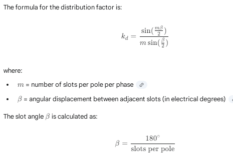
Distribution Factor ()
The distribution factor, also known as the breadth factor, accounts for the fact that the armature winding coils of each phase are not concentrated in a single slot under a pole, but are instead distributed across several slots. Because the EMFs in these distributed coils are out of phase with each other, the total EMF is the phasor sum, which is less than the arithmetic sum that would be obtained with a concentrated winding.
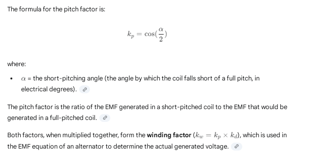
Pitch Factor ()
The pitch factor, also known as the coil span factor, accounts for the use of short-pitched windings. A full-pitched coil spans 180 electrical degrees (the distance between adjacent poles). A short-pitched coil has a span less than 180 degrees. Using short-pitched windings reduces the amount of conductor material needed and, more importantly, helps to eliminate or suppress specific harmonics in the generated voltage waveform, resulting in a more sinusoidal output. However, it also slightly reduces the fundamental EMF.
Click Here for MCQ Quiz Test:
Synchronous generator ( alternator) MCQ Part -01
Synchronous generator ( alternator) MCQ Part -02
Synchronous generator ( alternator) MCQ Part -03
Synchronous generator ( alternator) MCQ Part -04
Synchronous generator ( alternator) MCQ Part -05
Synchronous generator ( alternator) MCQ Part -06