Zener Diode
A Zener diode is a special type of silicon semiconductor diode that is designed to operate in the reverse breakdown region when the voltage exceeds a specific value known as the Zener breakdown voltage.
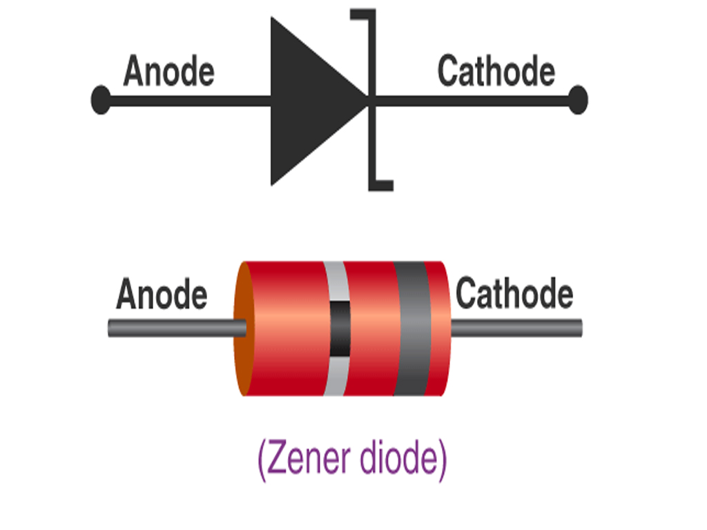
🔹 Symbol of Zener Diode:
🔹 Applications of Zener Diode
The unique characteristic of maintaining a nearly constant voltage across its terminals in the reverse breakdown region makes Zener diodes useful in various applications, including:
- Voltage Regulation: This is the most common application. When connected in parallel with a load and in series with a current-limiting resistor, a Zener diode maintains a relatively constant voltage across the load despite variations in the input voltage or load current.
- Over voltage Protection: Zener diodes can be used to protect sensitive circuits from voltage spikes.If the voltage exceeds the Zener voltage, the diode conducts and shunts the excess current to ground, preventing damage to other components.
- Voltage Reference:
- Due to their stable breakdown voltage, Zener diodes are used to provide a precise reference voltage in various electronic circuits.
- Clipping Circuits: Zener diodes can be used to limit or “clip” the amplitude of AC wave forms at a specific voltage level.
- Voltage Shifting:They can be used to shift the DC level of a signal.
- Temperature Compensation: Some Zener diodes exhibit a predictable voltage change with temperature and can be used to compensate for temperature-induced variations in other components.
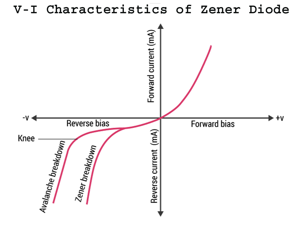
🔹 Zener Diode Characteristics:
1. Forward Bias Region:
- Works like a regular diode.
- Allows current to flow when forward voltage exceeds 0.7V (for silicon).
2. Reverse Bias Region:
- Minimal current flows until the reverse voltage reaches the Zener Breakdown Voltage.
- At V<sub>Z</sub>, the diode starts conducting in reverse to maintain a constant voltage.
Forward Characteristics of a Zener Diode
In the forward bias condition, a Zener diode behaves just like a regular PN junction diode. That means it starts conducting current once the forward voltage exceeds a certain threshold (typically ~0.7V for silicon).
✅ Key Points in Forward Bias:
- A threshold forward voltage (~0.7V for silicon).
- Exponential increase in current beyond that point.
- Behavior is identical to a regular diode in forward bias.
- At voltages less than 0.7V, only a tiny leakage current flows.
- Once V ≥ 0.7V, the diode conducts significantly, and current increases rapidly.
🔹 Reverse Characteristics of Zener Diode
In the reverse bias condition, the Zener diode behaves in a very distinct way compared to a regular diode. While a regular diode blocks reverse current up to its reverse breakdown voltage, the Zener diode is designed to conduct in reverse once a certain Zener breakdown voltage (V<sub>Z</sub>) is reached.
Key Regions in Reverse Bias:
- Pre-Breakdown Region (Reverse):
- Current is negligible until the voltage reaches V<sub>Z</sub>.
- The Zener diode behaves like a normal diode and does not conduct much. The diode behaves like an open switch (very low current).
- Breakdown Region:
- Once the reverse voltage exceeds the Zener voltage (V<sub>Z</sub>), the diode starts conducting in the reverse direction.
- The reverse current increases significantly, but the voltage remains constant at V<sub>Z</sub>.
- Post-Breakdown Region:
- The voltage stays constant at V<sub>Z</sub> even if the reverse current increases, ensuring stable voltage regulation.
🔹 Condition for Zener Breakdown
To function correctly and provide voltage regulation, a Zener diode must be operated under specific conditions:
- Reverse Bias: The Zener diode must be connected in reverse bias, meaning the cathode (K) is connected to the positive side of the voltage source, and the anode (A) is connected to the negative side.
- Reverse Voltage Greater Than or Equal to Vz: The applied reverse voltage across the Zener diode must be at least equal to its Zener voltage (Vz) to enter the breakdown region and provide voltage regulation. Ideally, it should be slightly above Vz to ensure stable operation.
- Operating Current Within Limits (Iz(min) to Iz(max)): The reverse current through the Zener diode must be maintained within its specified minimum (Iz(min)) and maximum (Iz(max)) limits.
- Iz(min): A minimum current is required for the diode to stay in the stable breakdown region and provide effective voltage regulation. If the current falls below this value, the voltage across the diode may become unregulated and drop below Vz.
- Iz(max): The maximum current is limited by the power dissipation rating of the diode (Pz = Vz * Iz(max)). Exceeding this limit will cause the diode to overheat and potentially fail. A series resistor is typically used to limit the current.
- Proper Power Dissipation Management: The power dissipated by the Zener diode (Pz = Vz * Iz) must be within its rated power dissipation. This ensures that the diode does not overheat and fail. The series resistor in a voltage regulator circuit helps to manage this power dissipation.
🔹 Example: Voltage Regulator Circuit
- Input Voltage: 12V
- Zener Diode: 5.6V
- The output across the Zener diode will remain approximately 5.6V, protecting sensitive components.
Proving that a Zener Diode Works in Combination Clippers
A combination clipper circuit is a circuit that clips a signal, typically a voltage, at certain levels using diodes. A Zener diode is particularly useful in this scenario because it can clip the signal at a specific, constant voltage (known as the Zener voltage) in the reverse bias.
In a combination clipper, we can combine two diodes (one regular diode and one Zener diode) to clip the input waveform in both positive and negative directions at specific voltage levels. Let’s prove how a Zener diode works in this configuration.
Zener Diode as a Clipper in a Combination Clipper Circuit
To understand how a Zener diode works in a combination clipper, let’s analyze the combination clipper circuit made up of:
- A regular diode (D₁) – to clip the signal at a specific level.
- A Zener diode (D₂) – to clip the signal at a reverse voltage level (known as the Zener voltage).
Consider the circuit below, where we apply an input signal (AC or DC) and clip it at both the positive and negative voltage levels using the diodes.
How the Zener Diode Clips the Signal
1. For Positive Half of Input (Input Voltage > 0)
- D₁ (regular diode) will turn ON when the input voltage reaches V<sub>f</sub> (~0.7V for silicon).
- It will conduct and clip the signal at V<sub>f</sub>. The output will be a constant voltage (near V<sub>f</sub>) for positive voltages greater than V<sub>f</sub>.
2. For Negative Half of Input (Input Voltage < 0)
- D₂ (Zener diode) will remain off until the reverse voltage exceeds the Zener breakdown voltage (V<sub>Z</sub>).
- Once the reverse voltage reaches V<sub>Z</sub>, the Zener diode will turn on and start conducting.
- The output voltage will be clipped at V<sub>Z</sub> in the negative direction (since the Zener diode maintains a constant voltage once it is in breakdown).
Proof: Zener Diode in Reverse Bias as a Clipper
- Reverse Bias Condition for Zener Diode:
- In reverse bias, the Zener diode behaves like an open switch until the reverse voltage exceeds the Zener breakdown voltage (V<sub>Z</sub>).
- Once this voltage is exceeded, the Zener diode starts to conduct and clamp the output to V<sub>Z</sub> (the Zener voltage), no matter how high the reverse voltage gets.
Thus, the Zener diode clips the signal at V<sub>Z</sub> and prevents it from going further negative, achieving the desired clipping effect.
Conclusion:
- Regular Diode (D₁): Clips the positive voltage at approximately V<sub>f</sub> (forward voltage).
- Zener Diode (D₂): Clips the negative voltage at the Zener breakdown voltage (V<sub>Z</sub>).
- The combination clipper uses the Zener diode’s reverse breakdown characteristic to clip the waveform at the Zener voltage.
Thus, we can prove that a Zener diode works in combination clippers by clipping the negative half of the waveform at the Zener voltage.
Frequently Asked Questions – FAQs
Question-1. What is a Zener diode?
Answer: A Zener diode is a special type of diode designed to operate in the reverse breakdown region and maintain a constant voltage across its terminals.
Question-2. What is Zener breakdown voltage?
Answer: It is the voltage at which a Zener diode starts conducting in reverse bias and maintains a stable voltage, called the Zener voltage.
Question-3. How is a Zener diode different from a regular diode?
Answer: A regular diode blocks reverse current, while a Zener diode is designed to conduct in reverse once the voltage exceeds, making it useful for voltage regulation.
Question-4. Can a Zener diode conduct in forward bias?
Answer: Yes. In forward bias, it behaves like a normal diode, conducting when the voltage exceeds ~0.7V (for silicon).
Question-5. What is the main application of a Zener diode?
Answer: The primary application is voltage regulation—it keeps the output voltage constant regardless of input fluctuations.
Question-6. What happens if Zener current exceeds the maximum rating?
Answer: Exceeding the rated current may overheat and damage the Zener diode. A current-limiting resistor is usually added in series.
Question-7. Can Zener diodes be used in AC circuits?
Answer: Yes, they are often used in clipping circuits and wave shapers for AC signals, in combination with other components.
Question-8. What is a Zener voltage regulator?
Answer: It is a circuit where a Zener diode maintains a constant output voltage, despite variations in input voltage or load conditions.
Question-9. What is the voltage tolerance of a Zener diode?
Answer: Voltage tolerance of a Zener diode is typically ±5%.
Question-10. State true or false: Zener diode is used as a shunt voltage regulator.
Answer: Yes, for regulating voltage across small loads, the Zener diode is used as a shunt voltage regulator.