Synchronous generators:
A synchronous generator (also called a alternator) is a type of electrical generator that that converts mechanical power into AC electrical power. It’s called “synchronous” because the speed of the rotor (the rotating part) is synchronized with the frequency of the generated AC current. It operates at a constant speed, meaning the rotor’s rotational speed is synchronized with the frequency of the AC power it generates. In other words, the speed of the generator’s rotor is directly related to the frequency of the AC power produced, typically via the relationship:
Speed (rpm) =120×Frequency (Hz)/Number of poles
An alternator’s output frequency depends on the number of poles and the rotational speed. The speed corresponding to a particular frequency is called the synchronous speed. This table gives some examples:
| Poles | Rotation speed (r/min), giving… | ||
| 50 Hz | 60 Hz | 400 Hz | |
| 2 | 3,000 | 3,600 | 24,000 |
| 4 | 1,500 | 1,800 | 12,000 |
| 6 | 1,000 | 1,200 | 8,000 |
| 8 | 750 | 900 | 6,000 |
| 10 | 600 | 720 | 4,800 |
| 12 | 500 | 600 | 4,000 |
| 14 | 428.6 | 514.3 | 3,429 |
| 16 | 375 | 450 | 3,000 |
| 18 | 333.3 | 400 | 2,667 |
| 20 | 300 | 360 | 2,400 |
| 40 | 150 | 180 | 1,200 |
Key Features of a Synchronous Generator:
- Constant Speed: The rotor speed must remain constant to maintain a fixed frequency of output AC. This is typically controlled by a prime mover like a steam turbine or a hydro turbine.
- Magnetic Field: The rotor has a magnetic field (often created by field windings or permanent magnets), which induces an alternating current in the stator windings as the rotor spins.
- Synchronization: Synchronous generators must be synchronized to the grid they are supplying electricity to, meaning their speed must match the frequency of the grid.
- Power Factor: The generator can either operate at a leading, lagging, or unity power factor, depending on the load.
Construction of a 3-Phase Alternator
A 3-phase alternator (also called a 3-phase synchronous generator) is a machine designed to generate three-phase alternating current. It consists of two main parts:
- Stator
- Rotor
1. Stator
The stator is the stationary part of the alternator and consists of the following components:
- Core: The stator core is made of laminated sheets of silicon steel to reduce eddy current losses. These sheets are stacked together to form a cylindrical shape. The core provides a path for the magnetic flux generated by the rotor.
- Armature Windings: These are the copper windings placed in the stator slots. The stator windings are connected in a three-phase star or delta configuration, depending on the design. These windings generate three-phase AC when they are cut by the rotating magnetic field of the rotor.
- Slot Insulation: The windings are insulated using varnish or resin to prevent short circuits between turns and to improve the durability of the stator windings.
- Frame: The stator is housed in a frame that supports and protects the entire structure.
2. Rotor
The rotor is the rotating part of the alternator, and it creates a magnetic field that induces voltage in the stator windings. There are two main types of rotors used in 3-phase alternators:
a) Salient Pole Rotor (or Projected Pole Rotor)
- Construction: The salient pole rotor has large poles that project out from the rotor shaft. These poles are wound with field windings, which are supplied with DC current to create a magnetic field.
- Working: The rotor’s poles rotate, and the rotating magnetic field interacts with the armature windings in the stator, inducing a 3-phase voltage.
- Application: Salient pole rotors are used in low-speed alternators (such as hydroelectric power plants) because they are better suited for machines that operate at slower speeds.
b) Non-Salient Pole Rotor (Cylindrical Rotor)
- Construction: The non-salient pole rotor has a smooth cylindrical surface, and it is typically made of laminated sheets of steel. The field windings are placed on the rotor in the form of a damper winding, which can also be used to reduce oscillations.
- Working: The magnetic field is generated by the rotor windings, and as it rotates, it induces an alternating current in the stator windings.
- Application: Non-salient pole rotors are used in high-speed alternators, such as those found in thermal power plants or in industrial applications where the alternator operates at higher speeds.
3. Field Winding or Exciter (for rotor magnetization)
The rotor in both types of alternators (salient or non-salient) requires a source of DC current to generate the magnetic field. This current is supplied to the rotor winding through an external exciter or a separate alternator (known as the exciter). The exciter provides a constant DC current to the field winding, which then generates the required magnetic field.
Working Principle of a 3-Phase Alternator
The working principle of a 3-phase alternator is based on Faraday’s Law of Electromagnetic Induction, which states that a voltage is induced in a conductor when it moves through a magnetic field. In the case of an alternator:
- Magnetic Field Creation: The rotor, which is supplied with DC current through an exciter, creates a magnetic field. In a salient pole rotor, the magnetic poles are physically protruding, while in a cylindrical rotor, the magnetic field is generated by the rotor’s field windings.
- Rotation of the Rotor: As the rotor spins, the magnetic field created by the rotor rotates along with it. The rotor speed is synchronized with the frequency of the generated AC power.
- Induction of Voltage in Stator Windings: The rotating magnetic field of the rotor cuts through the stator windings. According to Faraday’s Law, as the magnetic flux linked with the stator windings changes, an electromotive force (EMF) or voltage is induced in the stator windings. Since the rotor rotates continuously, this results in an alternating voltage in the stator windings.
- Three-Phase Voltage: The alternator is designed such that the stator windings are placed at 120° electrical angle from each other. This ensures that three separate voltage waveforms are induced, each shifted by 120° from the others. These three voltages form a three-phase system, which is widely used for power generation and distribution.
- Synchronization: The alternator must be synchronized to the grid frequency, meaning the speed of the rotor must match the frequency of the alternating current. The number of poles of the rotor determines the relationship between the speed and the frequency of the alternator.
Frequency of induced e.m.f of 3 phase alternator:
The frequency of the induced EMF in a 3-phase alternator (synchronous generator) is directly related to the speed of the rotor and the number of poles in the machine. Here’s the formula:
f = (P * N) / 120
Where:
- f is the frequency of the induced EMF in Hertz (Hz)
- P is the number of poles in the alternator
- N is the speed of the rotor in revolutions per minute (RPM)
Explanation:
- Poles: Alternators have north and south poles that create the magnetic field. 1 More poles mean more magnetic field changes per revolution.
- Speed: The faster the rotor spins, the more times the magnetic field cuts across the stator windings per second.
Example:
A 3-phase alternator has 4 poles and rotates at 1800 RPM. The frequency of the induced EMF is:
f = (4 * 1800) / 120 = 60 Hz
This is the standard frequency for AC power in many countries.
- Distribution Factor (Kd): In an alternator, the coils are not concentrated in a single slot under each pole. Instead, they are distributed in multiple slots. The distribution factor accounts for the fact that the EMFs induced in these coils are slightly out of phase with each other. If all the coils were concentrated in one slot, the EMFs would add up directly. But because they are distributed, the total EMF is slightly less. The distribution factor (Kd) represents the ratio of the actual EMF obtained with distributed windings to the EMF that would be obtained with concentrated windings.
Distribution factor (Kd) = e.m.f with distributed winding / e.m.f with concentrated winding.
- Formula: Kd = (sin(mβ/2)) / (m * sin(β/2))
Where: m = number of slots per pole per phase
β = slot angle (electrical degrees) = (180° * P) / S
P = number of poles
S = number of slots.
- Typical values: Always less than 1. The more slots per pole per phase, the lower the distribution factor.
- Pitch Factor (Kp): Ideally, the coil span of an alternator winding should be equal to the pole pitch (180 electrical degrees). However, in practice, it is often made shorter than the pole pitch. This is called short-pitching or chording. The pitch factor accounts for the reduction in EMF due to short-pitching. Short-pitching helps to reduce harmonics in the generated voltage waveform. However, it also reduces the fundamental component of the EMF. The pitch factor (Kp) represents the ratio of the EMF induced in a short-pitched coil to the EMF induced in a full-pitched coil.
Pitch Factor (Kp) = EMF induced in a short-pitched coil / EMF induced in a full-pitched coil.
- Formula: Kp = cos(α/2)
Where: α = the angle by which the coil span falls short of the pole pitch (electrical degrees)
- Typical values: Always less than 1. The more the coil is short-pitched, the lower the pitch factor.
- Winding Factor (Kw): The winding factor is the combined effect of the distribution factor and the pitch factor on the induced EMF. The winding factor is used to calculate the actual EMF generated by an alternator.
- Formula: Kw = Kd * Kp
EMF equation of an alternator:
The EMF equation of an alternator is used to calculate the induced electromotive force (EMF) or voltage generated in the stator windings of an alternator. This equation is derived based on Faraday’s Law of Electromagnetic Induction, which states that an EMF is induced in a conductor when it cuts magnetic flux.
The general formula for the induced EMF (E) in a 3-phase alternator is given by:
E = 4.44 * f * Φ * T * Kw
Where,
- E (Volts): This is the RMS (root mean square) value of the induced EMF (voltage) in one phase of the alternator. RMS is used because it’s the effective value of the AC voltage.
- 44: This is a constant derived from the formula for the RMS value of a sinusoidal waveform. It combines factors like the form factor and pi.
- f (Hertz): The frequency of the AC voltage. It’s determined by how fast the alternator’s rotor spins and how many poles it has. (f = (P * N) / 120, where P is the number of poles and N is the speed in RPM).
- Φ (Webers): The magnetic flux per pole. This is the amount of magnetic field produced by each pole of the rotor. A stronger magnetic field means more voltage.
- T (Turns): The number of turns of wire in each phase winding on the stator. More turns mean more voltage.
- Kw (Unitless): Winding factor (a correction factor that accounts for the distribution and the pitch of the stator coils).
The winding factor Kw accounts for the distribution and pitch of the stator coils.
- Distribution Factor (Kd): It accounts for the fact that the coils are not placed exactly in one slot but are distributed over several slots.
- Pitch Factor (Kp): It compensates for the fact that the coils are not fully pitched (placed at 180 degrees electrical) due to design considerations. The combination of these factors gives the winding factor:
Kw=Kd⋅Kp
The winding factor reduces the effective number of turns, so Kw typically ranges from 0.85 to 1.0, depending on the coil design.
3-Phase Alternator on No Load:
A 3-phase alternator operating at no load means that its terminals are open-circuited, and no external load is connected to it. A 3-phase alternator at no load is essentially generating voltage but not delivering any power to an external circuit. This condition is important for testing, analysis, and understanding the alternator’s fundamental characteristics.
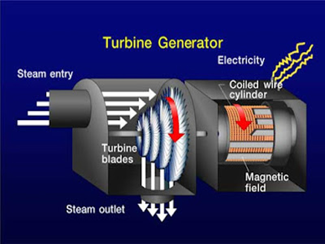
- Prime Mover:
- The alternator’s rotor is being driven by a prime mover (e.g., a turbine, engine). This provides the mechanical energy needed to rotate the rotor.
- Field Excitation:
- A DC current is supplied to the rotor’s field windings. This creates a strong magnetic field around the rotor.
- Induced EMF:
- As the rotor spins, its magnetic field cuts across the stator windings. This induces an alternating electromotive force (EMF) in the stator windings, according to Faraday’s law of electromagnetic induction.
- Open Circuit:
- Since there is no external load connected, no current flows through the stator windings. However, the EMF is still generated.
- Terminal Voltage:
- The voltage measured across the alternator’s terminals is the induced EMF. This is often referred to as the “open-circuit voltage” or “no-load voltage.”
- Factors Affecting No-Load Voltage:
- Rotor speed: Higher speed means a faster-changing magnetic field, resulting in a higher induced EMF.
- Field excitation: A stronger magnetic field (higher field current) also leads to a higher induced EMF.
- No-Load Characteristics:
- The relationship between the field current and the open-circuit voltage is called the “no-load characteristic” or “open-circuit characteristic” (OCC) of the alternator. This is an important graph used to understand the alternator’s behavior.
Why No-Load Operation is Important
- Testing and analysis: No-load tests are performed to determine the alternator’s characteristics and ensure it’s operating correctly.
- Voltage regulation: Understanding the no-load voltage is essential for designing voltage regulators that maintain a stable output voltage under varying load conditions.
- Synchronization: When connecting an alternator to a power grid, it’s crucial to match its no-load voltage and frequency with the grid’s voltage and frequency.
3-Phase Alternator on Load:
When a 3-phase alternator is on load, it means that it is supplying electrical power to an external load, and the alternator’s stator is delivering current to a connected circuit. The process involves both real power (active power) and reactive power being delivered to the load, and the alternator operates differently from the no-load condition.
When the alternator is loaded, the terminal voltages V changes due to the following effects.
Voltage Drop: Due to armature reaction and the impedance of the stator windings (resistance, Ra and reactance, XL) there’s a voltage drop across the alternator’s internal impedance. This means the terminal voltage (V) is less than the induced EMF (E).
Power Output:
- The alternator now delivers power to the load. The amount of power depends on the terminal voltage, the current, and the power factor of the load.
Mathematical Relationships
- Voltage Equation: V = E – Ia * (Ra + jXs)
Where:
* V = Terminal voltage per phase
* E = Induced EMF per phase
* Ia = Armature current per phase
* Ra = Armature resistance per phase
* Xs = Synchronous reactance per phase (accounts for armature reaction and stator leakage reactance)
The value of Xs is 10 to 100 times greater than Ra. Consequently, We can neglect Ra without any serious error.
Voltage Regulation of Three Phase Alternator:
Voltage regulation of an alternator refers to the ability of the alternator to maintain a constant output voltage despite changes in the load. It is an important characteristic of any power generation system because it ensures that the voltage supplied to the load remains stable, even as the load varies.
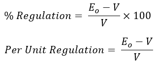
Mathematically, voltage regulation is defined as the difference between the no-load voltage and the full-load voltage, expressed as a percentage of the full-load voltage.
To understand voltage regulation mathematically, we need to consider the factors that cause voltage changes under load:
- Armature Reaction: The current flowing in the stator windings creates its own magnetic field, which interacts with the rotor’s field. This affects the net magnetic field and, consequently, the induced EMF.
- Internal Impedance: The stator windings have resistance and reactance, which cause a voltage drop when current flows.
Key Concepts
- No-Load Voltage (Eno−load): This is the terminal voltage of the alternator when there is no load connected to it, or when the alternator is running at synchronous speed but without any electrical load.
- Full-Load Voltage (Efull−load): This is the terminal voltage when the alternator is supplying full-rated load.
- Voltage Regulation: It indicates how much the terminal voltage decreases when a load is applied to the alternator. The higher the voltage regulation, the greater the drop in voltage when the load is applied.
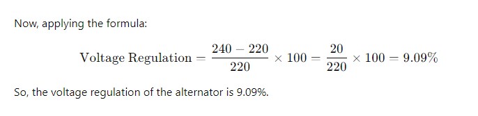
Example of Voltage Regulation Calculation:
Let’s assume an alternator has the following parameters:
- No-load voltage (Eno−load) = 240 V
- Full-load voltage (Efull−load)= 220 V
Types of Voltage Regulation:
- Under excited: The alternator’s excitation is lower than required, leading to a higher no-load voltage and lower voltage under load.
- Overexcited: The alternator’s excitation is higher than required, causing the no-load voltage to be lower and the full-load voltage to be higher.
- Synchronous: The alternator is balanced in terms of excitation, maintaining a relatively constant voltage with varying loads.
In practical scenarios, voltage regulation is an important consideration for designing and operating alternators, as it helps in ensuring the alternator provides stable power under different operating conditions.
Stable Power Supply: Many electrical devices require a stable voltage to operate correctly. Poor voltage regulation can lead to malfunctions or damage.
System Stability: In power systems, stable voltage is essential for maintaining overall system stability.
Major Losses in a 3-Phase Alternator
In a 3-phase alternator, various losses occur during its operation, which impact the efficiency of the machine. These losses result from the conversion of mechanical energy into electrical energy, and they can be classified into several categories based on their nature and the components in which they occur.
Here’s a breakdown of the main types of losses:
Copper Losses (I²R Losses)
These losses happen in the stator windings (armature windings) and the rotor windings (field windings) due to the resistance of the copper conductors. When current flows through a conductor, there’s always some energy dissipated as heat due to the conductor’s resistance. This is known as Joule heating or I²R loss. The magnitude of the current and the resistance of the windings. Higher current and higher resistance lead to greater copper losses.
Core Losses (Iron Losses):
- Core losses occur in the magnetic core of the alternator, which consists of the stator and rotor core.
- These losses include:
- Hysteresis Loss: Energy is lost due to the reversal of magnetization in the core material when the magnetic field alternates.
- Eddy Current Loss: Currents are induced in the core material due to the alternating magnetic flux, which leads to energy dissipation.
- Core loss is generally independent of the load and depends on the frequency and the flux density.
- The core material is usually made of silicon steel to minimize these losses.
Mechanical Losses
These losses occur in the moving parts of the alternator due to friction and air resistance.
- Types:
- Friction losses: These occur in the bearings, brushes (if used), and other contact surfaces due to friction.
- Windage losses: These are caused by the friction between the rotating parts (rotor) and the surrounding air or other medium inside the alternator casing.
The total mechanical loss depends on the design of the alternator and the speed at which it operates.
Stray Load Losses
These are miscellaneous losses that are difficult to determine precisely. They can be due to factors like:
- Distortion of the main field flux due to armature reaction. These losses are caused by the additional current that is induced in the stator and rotor due to stray fluxes in the air gaps and other components.
- Non-uniform distribution of current in the armature conductors.
- Losses in the connections and other small components.
These losses are often complex and difficult to isolate, so they are grouped together as stray losses. Various factors related to the load, design, and operating conditions of the alternator.
Brush and Slip Ring Losses (for alternators with slip rings):
- In alternators that use slip rings to supply current to the rotor winding, additional losses occur due to the friction and contact resistance at the brushes.
- These losses are relatively small but significant in certain types of alternators (especially those with larger outputs).
Insulation Losses:
- Insulation materials in the stator and rotor windings also contribute to losses, particularly due to leakage currents. These losses are generally small but can increase with higher operating temperatures.
Minimizing Losses
Designers and operators take various measures to minimize these losses:
- Using high-quality materials: For example, using high-conductivity copper for windings and laminating the core to reduce eddy current losses.
- Optimizing design: For example, minimizing friction in bearings and improving airflow to reduce windage losses.
- Operating at optimal conditions: For example, operating the alternator at its rated speed and load to minimize losses.
Understanding these losses is crucial for improving alternator efficiency, reducing operating costs, and ensuring reliable operation.
Efficiency of a 3-Phase Alternator
Efficiency (η) is defined as the ratio of output power to input power. It’s usually expressed as a percentage:
η = (Output Power / Input Power) * 100%
In the case of a 3-phase alternator:
- Output Power (Pout): This is the electrical power delivered by the alternator to the load. It can be calculated as: Pout = √3 * VL * IL * cos(φ)
Where:
* VL = Line voltage
* IL = Line current
* cos(φ) = Power factor of the load
- Input Power (Pin): This is the mechanical power supplied to the alternator’s rotor by the prime mover (e.g., turbine, engine). It’s often not directly measured but can be calculated by adding all the losses to the output power: Pin = Pout + Total Losses
Factors Affecting Efficiency
- Load: Efficiency generally varies with the load. It’s often highest near the rated full load of the alternator.
- Power Factor: A higher power factor generally leads to higher efficiency.
- Speed: The speed of the prime mover affects losses and can influence efficiency.
- Design: The design and construction of the alternator, including materials used and cooling systems, significantly impact efficiency.
Typical Values
Large alternators in power plants can have efficiencies in the range of 85% to 95% or even higher at their optimal operating point.
Importance of Efficiency
- Cost Savings: Higher efficiency means less energy is wasted, reducing operating costs.
- Resource Conservation: More efficient alternators make better use of energy resources.
- Reduced Heat Generation: Lower losses mean less heat is generated, improving reliability and lifespan.
What is Parallel Operation?
Parallel operation refers to connecting two or more alternators to the same busbar or power grid so they can supply power together. This is a common practice in power plants and large electrical systems. The alternators operate in parallel to share the total load and improve the overall reliability and efficiency of the power system.
Conditions for Parallel Operation
Voltage Synchronization: The alternators must operate at the same voltage to avoid circulating currents between them.
Frequency Synchronization: The frequency of the output voltage must be the same for all alternators.
Phase Sequence: The phase sequence (order of phases) must be the same for all alternators.
Load Sharing: The alternators must share the load in proportion to their ratings.
Synchronization
The process of ensuring these conditions are met before connecting the alternator is called synchronization. Various methods are used for synchronization, including:
- Lamps: Three lamps are connected between the alternator terminals and the grid terminals. When the alternator and grid are out of phase, the lamps flicker. When they are in phase, the lamps are dark (or very dim). This method is simple but less precise.
- Synchroscope: A meter that indicates the phase difference between the alternator and the busbar ( grid). The operator adjusts the alternator’s speed until the synchroscope needle points to zero (or a designated “in-phase” mark). This method is more precise.
- Automatic Synchronizers: Modern power plants often use automatic synchronizers that perform the synchronization process automatically, based on measurements of voltage, frequency, and phase.
The Synchronization Process
The goal of synchronization is to ensure that the incoming alternator is “in sync” with the grid or the existing alternator(s). This involves matching several key parameters:
- Voltage: The incoming alternator’s terminal voltage must be equal to the grid voltage. A voltmeter is used to check this.
- Frequency: The frequency of the alternator’s output must match the grid frequency. A frequency meter or a synchroscope can be used. Small adjustments to the prime mover’s speed control are made to achieve this.
- Phase Sequence: The order in which the voltage reaches its peak in each phase must be the same for the alternator and the grid. Incorrect phase sequence can cause a short circuit. Phase sequence indicators or lamps are used to verify this.
- Phase Angle: The voltage waveforms of the alternator and the grid must be in phase (or very nearly so). This is the most critical condition. A synchroscope is typically used to indicate the phase difference.
Steps Involved (using a Synchroscope):
- Check Voltage: Verify that the alternator voltage matches the grid voltage. Adjust the field excitation if necessary.
- Check Frequency: Verify that the alternator frequency is close to the grid frequency. Adjust the prime mover speed.
- Observe Synchroscope: Watch the synchroscope. If the needle is rotating slowly, it indicates a small frequency difference. Continue adjusting the prime mover speed to minimize the rotation.
- Close the Switch: When the synchroscope needle is at zero (or the designated in-phase mark) and the other conditions are met, the operator closes the switch connecting the alternator to the grid.
After Synchronization
Once the alternator is connected, it will share the load with the other alternators on the grid. The amount of power it delivers depends on its excitation and the governor setting of its prime mover.
Advantages of Parallel Operation of Alternators:
- Increased Reliability: If one alternator fails, the load can be shifted to the remaining alternators, providing redundancy and improving system reliability.
- Improved Load Sharing: Alternators can share the load, which ensures that no single alternator is overloaded, thereby increasing the operational lifespan of the alternators.
- Flexibility in Power Generation: The ability to connect multiple alternators allows for flexible power generation, enabling easy expansion and adjustment based on the load demand.
- Reduced Operating Costs: By operating alternators in parallel, the system can be optimized for fuel efficiency and cost-effectiveness. Under certain conditions, alternators can operate at their most efficient points, leading to fuel savings.
- Better Maintenance Scheduling: With parallel operation, maintenance can be done on one alternator while others continue to supply power, reducing downtime and ensuring continuous power availability.
- Capacity for Peak Loads: Parallel operation allows for additional alternators to be brought online during periods of high load demand, ensuring that the system can handle peak loads efficiently.
- Optimal Distribution of Power: Alternators in parallel can share the load according to their capacities, preventing a single machine from becoming overloaded.
- Efficiency: Operating multiple alternators at their optimal efficiency points can be more efficient than operating a single large alternator at varying loads.
Disadvantages of Parallel Operation
- Complexity: Parallel operation requires careful synchronization and control to ensure stability and prevent damage to the alternators.
- Circulating Currents: If the conditions for parallel operation are not met precisely, circulating currents can flow between the alternators, leading to losses and potential overheating.
- Fault Current: In the event of a fault, the fault current can be higher with parallel operation, requiring more robust protection systems.
- Stability Issues: Parallel operation can introduce stability challenges, especially with a large number of alternators. Careful control and coordination are needed to maintain system stability.
- Cost: The equipment and control systems required for parallel operation can be more expensive than for a single alternator system.
Parallel operation of alternators is essential for meeting large power demands and improving reliability in modern power systems. Parallel operation of alternators provides a means of ensuring uninterrupted power supply, flexibility, and efficiency, while also reducing the operational risks associated with power generation. However, it requires careful planning, synchronization, and control to ensure safe and efficient operation.
Hunting of Alternator:
Definition: Hunting is a phenomenon where the alternator rotor oscillates around its synchronous speed due to disturbances. This oscillation can cause instability in the system and result in fluctuations in the generated voltage and frequency. It can cause instability and stress on the equipment, but it can be mitigated through design features and control systems.
Hunting typically occurs when the alternator’s speed regulator fails to maintain a constant speed under varying load conditions. It results in the alternator continuously overcompensating and then undercompensating in response to load changes, leading to a repetitive “hunting” effect.
Causes of Hunting:
- Load Fluctuations: Rapid or large fluctuations in load can cause the alternator’s speed to fluctuate, as the alternator compensates for the change in demand. If the load change is too fast for the alternator to respond smoothly, it can lead to hunting.
- Inadequate Speed Control Mechanism: A malfunctioning or poorly designed speed governor can cause the alternator to oscillate in speed. A governor regulates the speed of the alternator by adjusting the fuel input to the prime mover (e.g., steam or diesel engine). If it cannot respond quickly or correctly to changes in load, hunting may occur.
- Poor Synchronization: If the alternator is not properly synchronized with other generators or the power grid, it can result in mismatched frequencies, causing oscillations in the alternator’s output.
- Oversensitivity of the Governor: If the governor system is too sensitive or overreacts to minor fluctuations in load, it can continuously adjust the alternator’s speed too much, leading to hunting.
- Incorrectly Set Load Sharing: In systems with multiple alternators running in parallel, improper load sharing between units can cause some alternators to work harder than others, leading to frequency variations and hunting.
- Inadequate Damping Mechanism: Some alternators may lack sufficient damping mechanisms in their speed control systems. Without proper damping, any speed fluctuations may persist, causing oscillations.
Prevention of Hunting:
- Proper Governor Adjustment: Ensuring that the governor is properly calibrated and responds appropriately to load variations is key in preventing hunting. The governor should not be too sensitive or too slow in responding to load changes.
- Damping Mechanisms: Adding or improving damping systems, such as mechanical or electrical dampers, can help suppress the oscillations caused by hunting.
- Stable Load Sharing: In systems with multiple alternators, proper load sharing among the generators ensures that no single generator is overburdened, helping to stabilize the system and prevent hunting.
- Use of Automatic Voltage Regulators (AVRs): AVRs help stabilize the voltage and minimize fluctuations in power supply, which can reduce the impact of hunting, especially in systems with multiple generators running in parallel.
- Regular Maintenance and Calibration: Routine checks and maintenance of alternator components (such as the governor, speed control system, and excitation system) ensure proper operation and prevent issues that could lead to hunting.
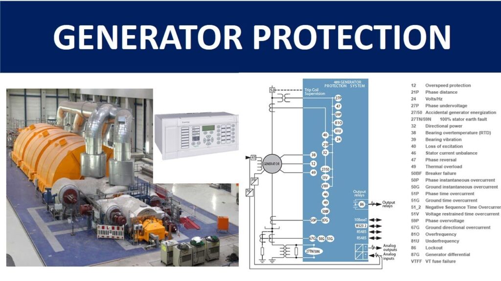
Protection for an alternator:
An alternator is a critical piece of equipment in any power generation system, and ensuring its protection is vital to avoid damage, maintain efficiency, and ensure the safety of both the alternator and the surrounding system. The protection required for an alternator depends on various factors, such as the alternator’s size, its application, and the environment in which it operates. Generally, the following types of protections are considered essential for an alternator:
1. Overload Protection
- Purpose: Protects the alternator from operating beyond its rated capacity, which could lead to overheating, mechanical damage, or failure.
- Protection Type: Overload relays, often integrated into the alternator’s control panel, help detect when the alternator is carrying more load than it is designed for and disconnect it from the system to prevent damage.
2. Short Circuit Protection
- Purpose: Protects the alternator from the effects of short circuits, which could cause excessive currents that damage both the alternator and the connected electrical system.
- Protection Type: Short-circuit protection can be achieved through circuit breakers and fuses. These devices disconnect the alternator from the system immediately when a short circuit is detected.
3. Under Frequency Protection
- Purpose: Prevents damage when the alternator’s frequency falls below the minimum acceptable level. Low frequency may indicate an overload, mechanical failure, or other issues affecting the alternator’s speed.
- Protection Type: Under-frequency relays monitor the alternator’s frequency and trigger a shutdown if the frequency drops too low, preventing potential damage due to prolonged operation at an incorrect frequency.
4. Over Frequency Protection
- Purpose: Protects the alternator from running at a higher-than-rated frequency, which could occur due to failure of the speed control system or other reasons. Excessive speed could damage the alternator’s mechanical components.
- Protection Type: Over-frequency relays monitor the alternator’s frequency and disconnect the alternator from the system if the frequency rises beyond safe levels.
5. Overvoltage Protection
- Purpose: Prevents damage to the alternator and the electrical system due to excessive voltage, which could be caused by a malfunction in the voltage regulator or the alternator’s excitation system.
- Protection Type: Overvoltage relays monitor the alternator’s output voltage and disconnect the alternator if it exceeds the safe limits.
6. Undervoltage Protection
- Purpose: Protects against prolonged operation at low voltage, which can be detrimental to both the alternator and the load.
- Protection Type: Undervoltage relays sense when the output voltage drops below a preset level and automatically disconnect the alternator to prevent damage or malfunction.
7. Reverse Power Protection
- Purpose: Prevents the alternator from running in reverse (i.e., when power flows back into the alternator). This situation can occur if the alternator is operating at a low speed or when the grid voltage is higher than the alternator’s output, potentially damaging the alternator’s rotor and stator.
- Protection Type: Reverse power relays monitor the direction of power flow and disconnect the alternator if reverse power is detected.
8. Bearing Temperature Protection
- Purpose: Protects the alternator’s bearings from overheating, which could be caused by friction, lubrication failure, or a mechanical issue.
- Protection Type: Temperature sensors and thermal relays monitor the bearing temperature and shut down the alternator if the temperature exceeds safe limits.
9. Field Failure Protection
- Purpose: Protects the alternator from a failure in the field excitation system, which could cause the alternator to lose voltage regulation or fail to produce the required output.
- Protection Type: Field failure relays monitor the field excitation circuit and disconnect the alternator if there is an issue with the excitation system.
10. Loss of Synchronism Protection
- Purpose: Prevents damage to the alternator when it gets out of synchronization with the grid or other alternators in parallel operation. Loss of synchronism can cause excessive currents and mechanical stresses.
- Protection Type: Synchronization protection systems (e.g., out-of-synchronism relays) detect when the alternator is not properly synchronized with the grid and automatically disconnect it.
11. Overload and Overcurrent Protection
- Purpose: Provides protection against excessive current that could damage the alternator’s windings, stator, and rotor.
- Protection Type: Overcurrent relays protect against high current levels, either caused by overloads or faults in the system.
12. Exciter Protection
- Purpose: Ensures the alternator’s exciter (which provides the field current for the alternator’s rotor) is operating correctly. If the exciter fails or behaves erratically, it can cause poor voltage regulation or loss of power output.
- Protection Type: Exciter protection systems monitor the exciter’s performance and trip the alternator if problems arise in the excitation system.
13. Differential Protection (Stator Earth Fault Protection)
- Purpose: Protects the alternator’s stator windings from internal faults, such as short circuits or earth faults, by detecting discrepancies in the input and output currents.
- Protection Type: Differential relays compare the current entering and leaving the alternator. If there’s a difference, the relay trips the alternator to prevent further damage.
14. Vibration Monitoring and Protection
- Purpose: Prevents mechanical damage caused by abnormal vibrations in the alternator, which can be caused by misalignment, imbalance, or wear.
- Protection Type: Vibration sensors monitor the alternator’s vibration levels and activate protective shutdown procedures if the levels exceed safe thresholds.
Click Here for MCQ Quiz Test:
Synchronous generator ( alternator) MCQ Part -01
Synchronous generator ( alternator) MCQ Part -02
Synchronous generator ( alternator) MCQ Part -03
Synchronous generator ( alternator) MCQ Part -04
Synchronous generator ( alternator) MCQ Part -05
Synchronous generator ( alternator) MCQ Part -06