Programmable Logic Controllers (PLC):
A Programmable Logic Controller (PLC) is a specialized industrial computer designed to control and automate electromechanical processes. PLCs are widely used in manufacturing plants, power stations, oil and gas industries, water treatment plants, and many other industrial environments where reliability, flexibility, and real-time control are critical.
Before the introduction of PLCs, industrial control systems were mainly based on relay logic. These systems were bulky, difficult to modify, consumed more power, and required extensive wiring. Any change in the control logic meant physically rewiring the entire system. PLCs were developed to overcome these limitations by replacing hard-wired relays with software-based logic.
A PLC continuously monitors input signals from sensors and switches, processes these signals according to a user-defined program, and then controls output devices such as motors, valves, relays, and actuators. Because PLCs are designed for harsh industrial environments, they can withstand high temperatures, vibrations, dust, and electrical noise.
Today, PLCs play a central role in industrial automation, helping industries improve productivity, reduce human error, ensure safety, and achieve consistent product quality.
Working Principle of PLC:

[PLC and I/O module diagrams]
The working principle of a PLC is based on a continuous cyclic operation known as the scan cycle. The PLC operates by repeatedly performing a sequence of steps that allow it to monitor inputs, execute logic, and control outputs in real time.
Step-by-Step Working Process
- Input Scanning
The PLC reads the status of all connected input devices such as push buttons, limit switches, sensors, and proximity detectors. These signals may be digital (ON/OFF) or analog (voltage or current values). - Program Execution
The PLC executes the control program stored in its memory. This program is written using a PLC programming language such as Ladder Logic or Function Block Diagram. The logic determines how outputs should respond to the current input conditions. - Output Update
Based on the program execution results, the PLC updates the status of output devices. Outputs may include motors, solenoid valves, indicator lamps, contactors, or alarms. - Communication and Diagnostics
Many PLCs also perform communication tasks with HMIs, SCADA systems, or other PLCs while checking system health and fault conditions.
This entire process repeats continuously within milliseconds, ensuring fast and accurate control of industrial processes.
Components of a PLC System
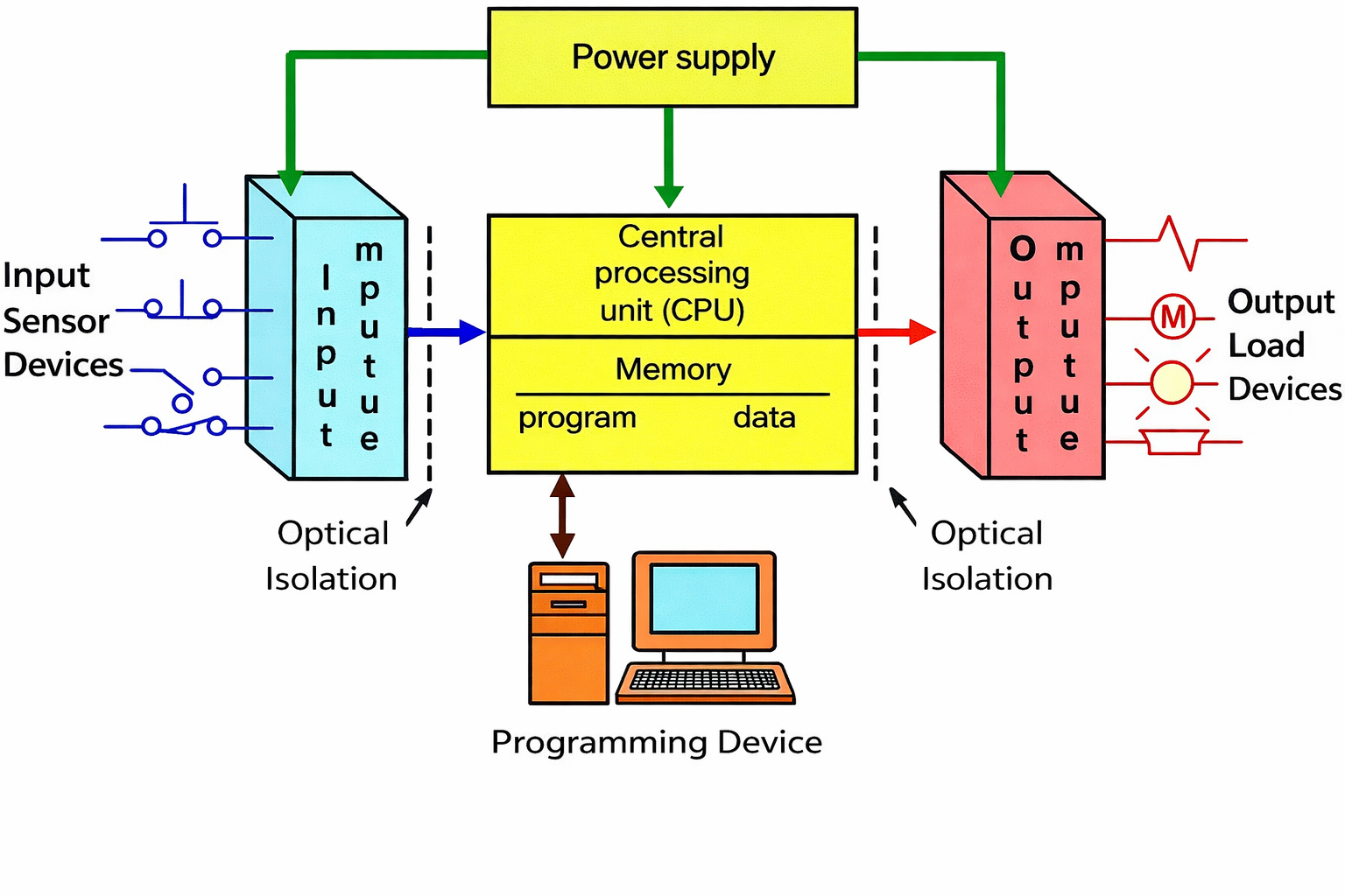
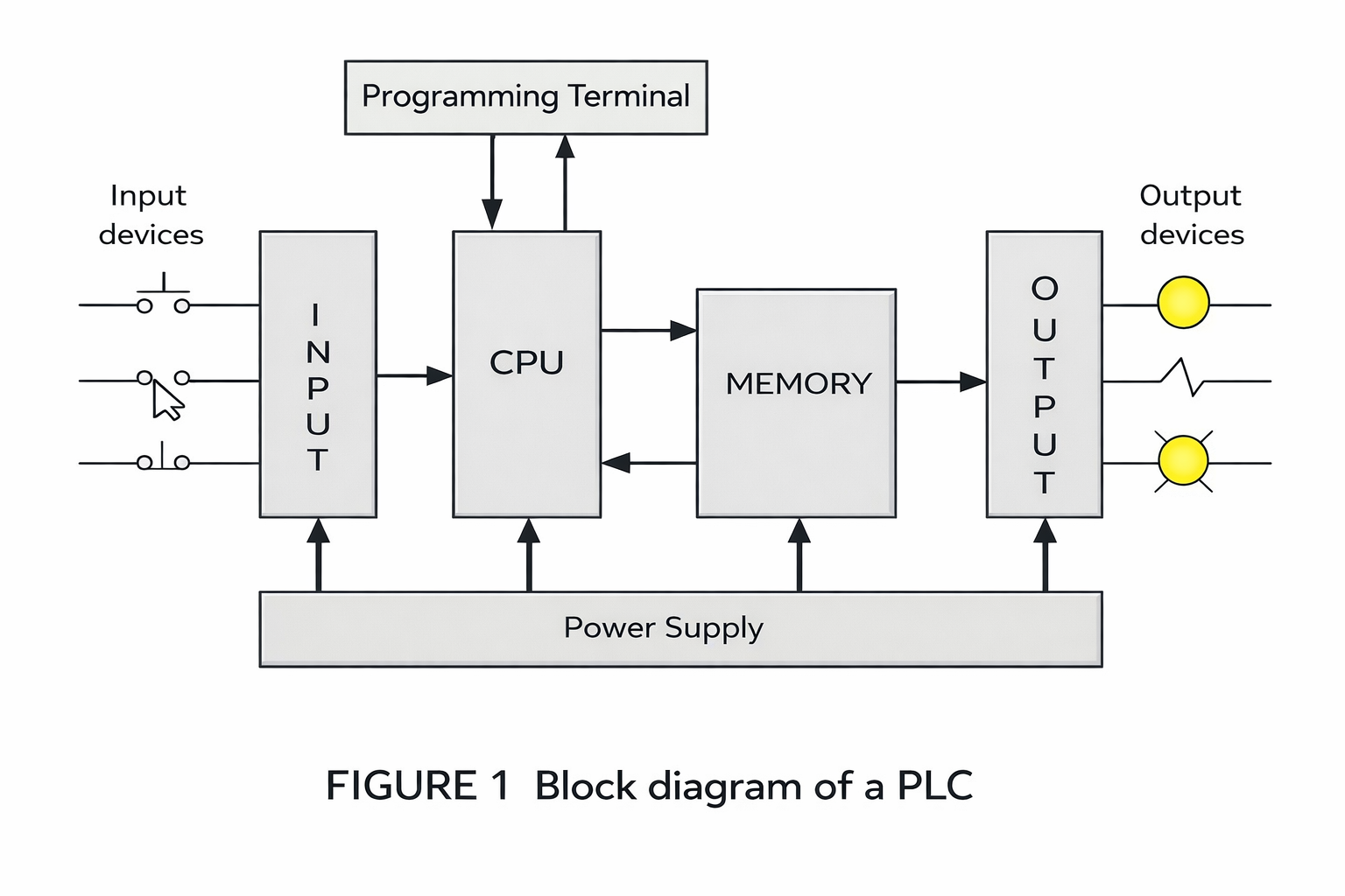
[PLC system architecture diagram]
A PLC system consists of several key hardware components that work together to perform automation tasks.
3.1 Power Supply
The power supply converts the available AC or DC power into the required voltage levels for PLC operation. It ensures stable and uninterrupted power for internal circuits.
3.2 Central Processing Unit (CPU)
The CPU is the brain of the PLC. It executes the control program, processes input data, updates outputs, performs diagnostics, and manages communication.
3.3 Input Modules
Input modules receive signals from field devices such as switches, sensors, and transmitters. They convert real-world electrical signals into logic signals that the CPU can understand.
3.4 Output Modules
Output modules send control signals from the PLC to field devices like motors, relays, and valves. Outputs may be either digital or analog, depending on the application.
3.5 Memory
PLC memory stores the control program, I/O data, and system configuration. It includes ROM, RAM, and non-volatile memory.
3.6 Communication Modules
These modules allow PLCs to communicate with HMIs, SCADA systems, drives, and other PLCs using industrial communication protocols.
PLC vs Relay Logic Control Systems:
Before PLCs, relay-based control systems were widely used in industries. Although effective at the time, relay logic systems have several disadvantages compared to PLCs.
Comparison Overview
| Feature | Relay Logic | PLC |
| Flexibility | Low | High |
| Wiring Complexity | Very High | Minimal |
| Maintenance | Difficult | Easy |
| Modification | Time-consuming | Software-based |
| Size | Bulky | Compact |
| Speed | Slow | Very Fast |
PLCs offer greater reliability, easy troubleshooting, lower downtime, and scalability, making them the preferred choice for modern automation systems.
PLC Programming Languages
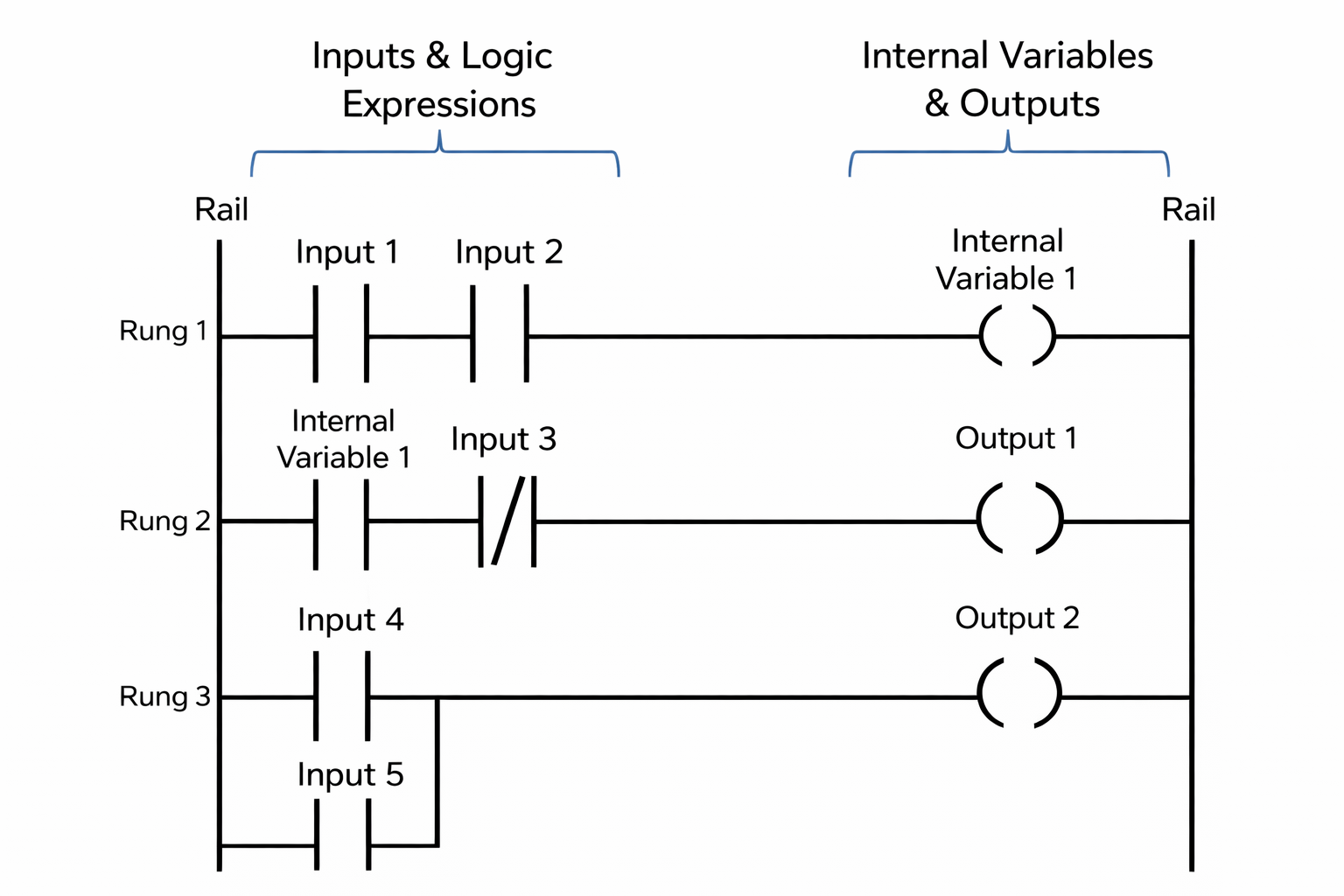
[Ladder logic diagram overview]
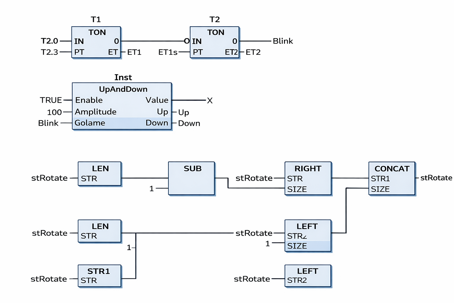
[PLC diagram with timers and string manipulations]
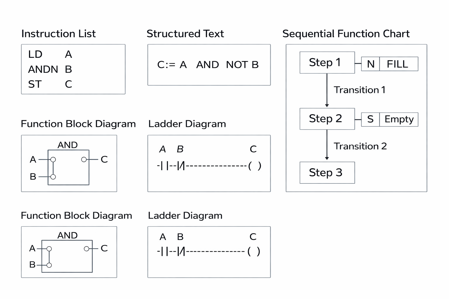
[PLC programming languages breakdown]
PLC programming languages are standardized under IEC 61131-3. Each language suits different application requirements.
5.1 Ladder Logic (LD)
Ladder Logic resembles electrical relay diagrams, making it easy for electricians and technicians to understand. It uses contacts and coils to represent logic operations.
5.2 Function Block Diagram (FBD)
FBD uses graphical blocks connected by lines to represent signal flow. It is ideal for analog control and process automation.
5.3 Structured Text (ST / STL)
Structured Text is a high-level programming language similar to C or Pascal. It is suitable for complex calculations and advanced control algorithms.
5.4 Sequential Function Chart (SFC)
SFC is used for sequential operations where steps and transitions must follow a specific order, such as batch processing systems.
Scan Cycle of a PLC
The scan cycle is the fundamental operating sequence of a PLC.
Scan Cycle Stages
- Input Scan
- Program Scan
- Output Scan
- Housekeeping Tasks
The scan time depends on program complexity, PLC speed, and number of I/O points. Faster scan times are essential for high-speed control applications.
Ladder Logic Programming Explained:
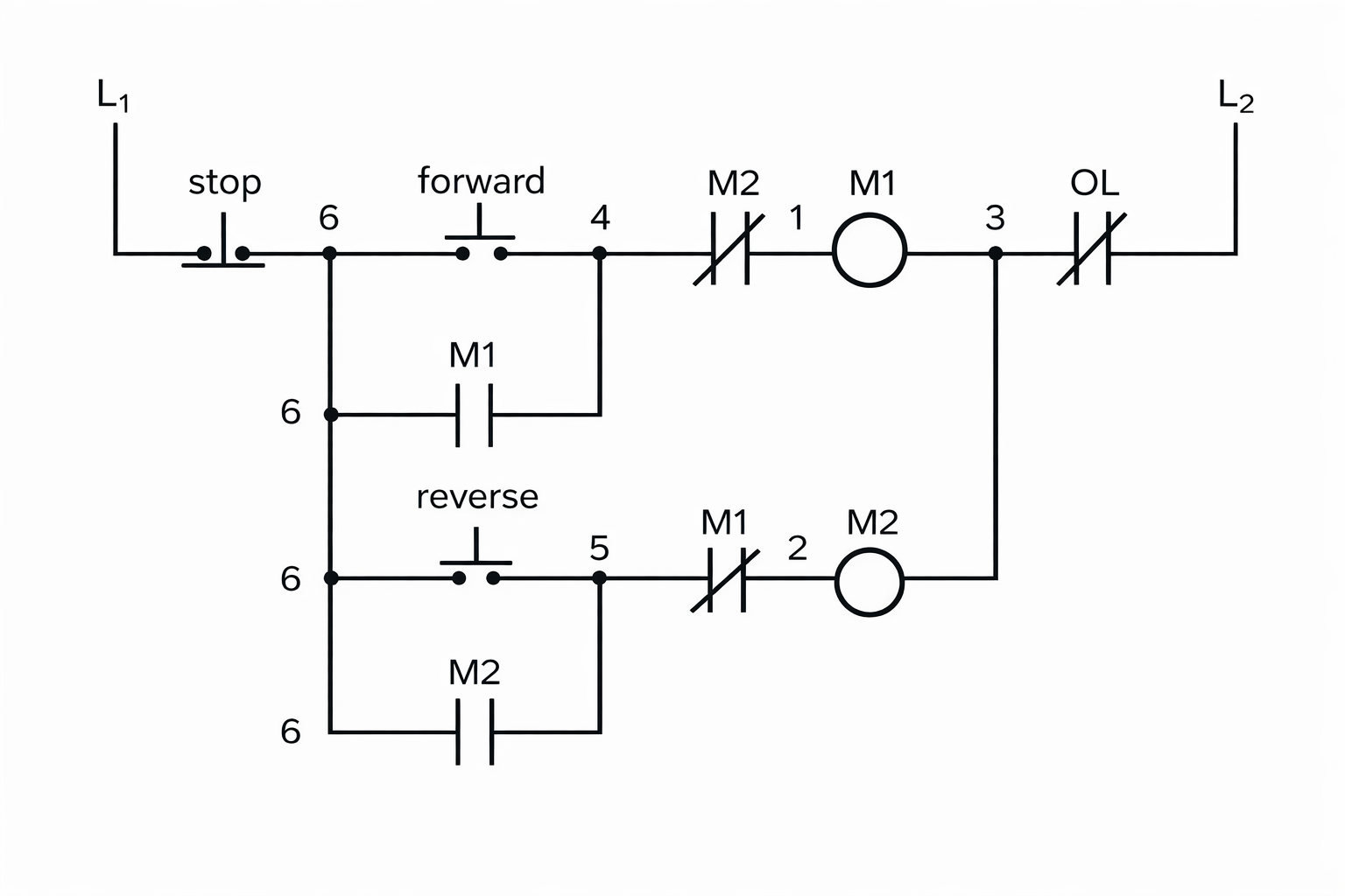
[Basic motor control circuit diagram]
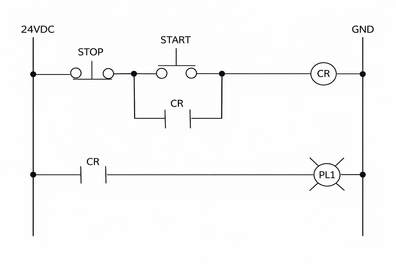
[Basic control circuit schematic diagram]
Ladder Logic is the PLC programming language most commonly used.
Key Elements
- Contacts: Represent input conditions
- Coils: Represent output actions
- Timers: Control time-based operations
- Counters: Count events or pulses
Example: A simple motor start-stop circuit uses push buttons as inputs and a motor contactor as output.
PLC Programming for Beginners:
PLC programming for beginners focuses on understanding:
- Digital inputs and outputs
- Basic logic operations (AND, OR, NOT)
- Timers and counters
- Simple troubleshooting techniques
Beginners usually start with simulation software before working on real PLC hardware.
Industrial Automation Using PLC:

[Industrial automation with PLCs in action]
Industrial automation using PLCs improves efficiency, accuracy, and safety. PLCs control production lines, packaging systems, robotic arms, and conveyor belts.
Benefits
- Reduced labor cost
- Improved product quality
- Increased production speed
- Enhanced safety
PLC in Manufacturing Industries:
PLCs are extensively used in:
- Automotive assembly lines
- Food and beverage processing
- Textile industries
- Cement and steel plants
They ensure consistent production and allow rapid changes in manufacturing processes.
PLC-Based Motor Control Systems:
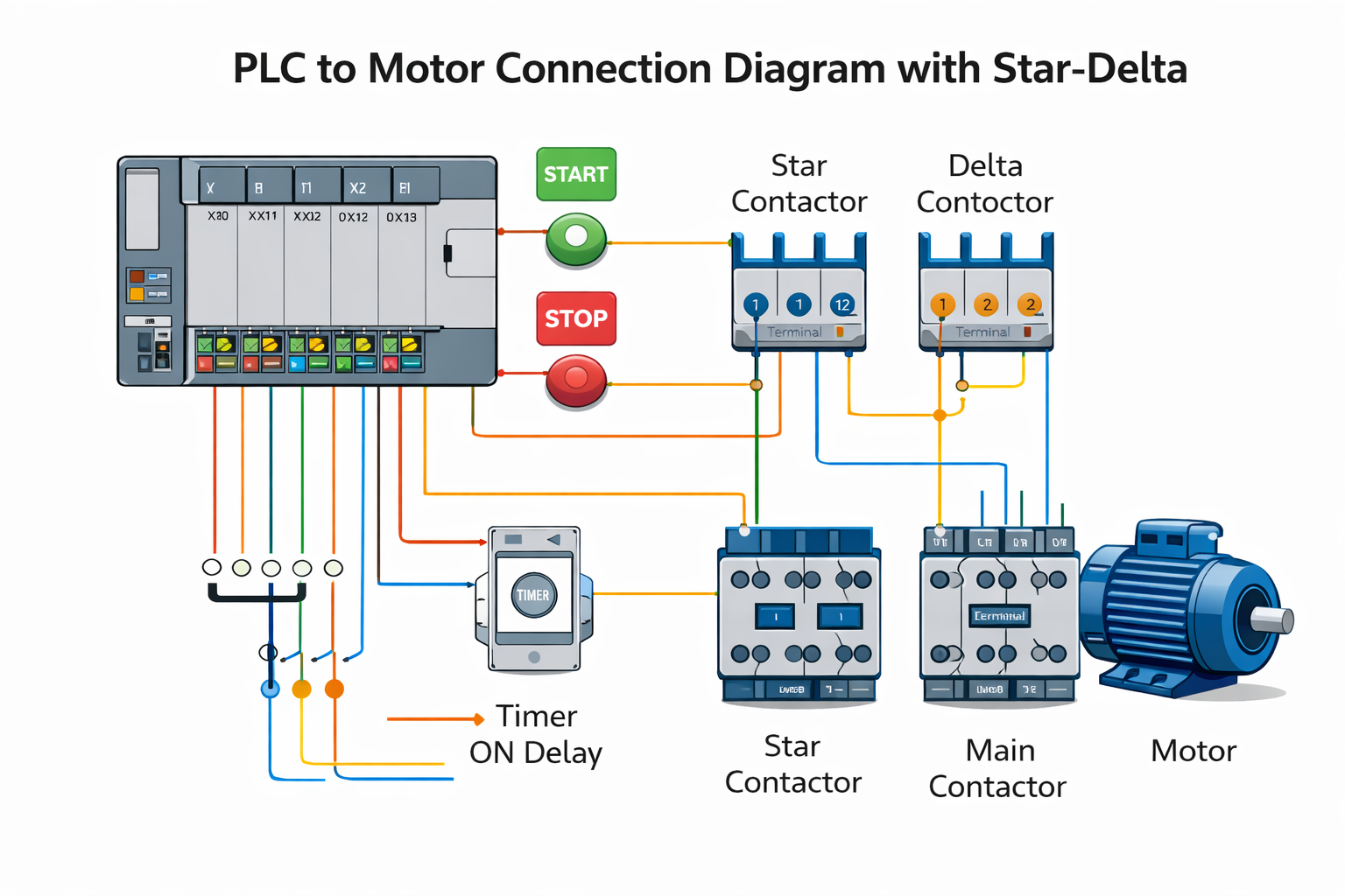
[PLC to motor star-delta configuration diagram]
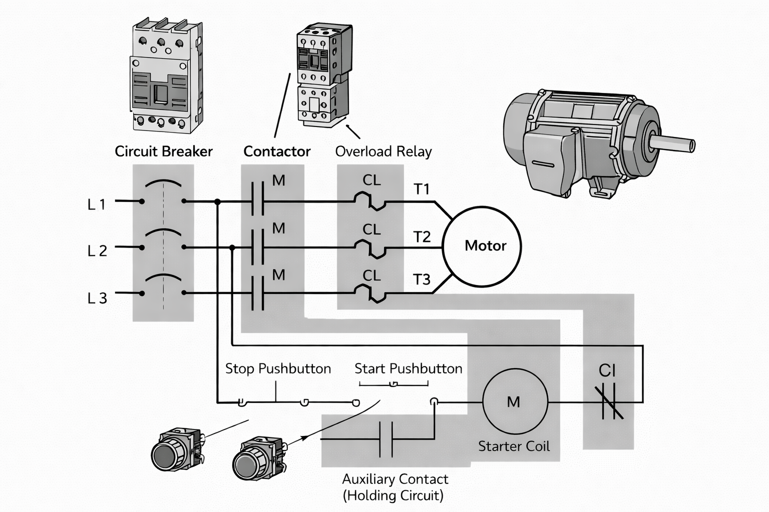
[Motor control circuit diagram]
PLCs control motors using techniques such as:
- Direct Online (DOL) starting
- Star-delta starting
- Variable Frequency Drive (VFD) control
PLC-based motor control improves efficiency, protection, and automation.
PLC Applications in Process Control:
Process control industries such as chemical plants, oil refineries, and power plants use PLCs to control:
- Temperature
- Pressure
- Flow
- Level
PLCs provide real-time monitoring and precise control, ensuring safe and stable operations.
Programmable Logic Controllers have revolutionized industrial control systems by replacing traditional relay-based logic with flexible, software-driven automation. From basic motor control to complex process automation, PLCs are indispensable in modern industries. Understanding PLC fundamentals, programming techniques, and applications is essential for every Electrical and Electronic Engineering student aiming to build a career in industrial automation.