Static Relays
In modern power system protection, relays play a crucial role in detecting faults and initiating isolation of the faulty section to maintain stability and reliability. For decades, electromagnetic relays were the standard devices for protection. However, with technological advancement and the demand for faster, more reliable, and compact systems, static relays have become an essential part of electrical protection schemes.
Table of Content of Static Relays
- Definition
- Main Components of Static Relays
- Working Principle of Static Relays
- Types of Static Relays
- Static Relays vs Electromagnetic Relays
- Advantages of Static Relays
- Disadvantages of Static Relays
- Applications of Static Relays
- Conclusion
1.0: Definition:
A static relay is a type of protective relay in which the response to the input signal is achieved by electronic or static components without any moving parts such as coils, armatures or mechanical contacts used in traditional electromagnetic relays. In simple terms, a static relay uses solid-state electronic circuits—like resistors, capacitors, diodes, transistors, operational amplifiers, and logic gates—to perform measurement and decision-making functions.
The word “static” indicates that the relay operates without the motion of mechanical parts during the decision-making process. However, it’s important to note that some static relays may still use an electromagnetic output element, such as a tripping relay or circuit breaker coil, to complete the final tripping operation.
1.1: Historical Background:
The development of static relays began in the 1950s and 1960s, when the use of vacuum tubes and early solid-state devices became practical for power system protection. These relays offered improved performance compared to their electromagnetic counterparts, particularly in speed, sensitivity, and accuracy. Over time, static relays evolved into microprocessor-based digital relays and eventually into numerical relays, which are the current standard.
1.2: Basic Concept:
A static relay works on the principle of comparing an electrical quantity (such as current, voltage, frequency, or power) with a preset threshold. When the measured quantity exceeds this threshold, the relay issues a command signal to trip the circuit breaker and isolate the faulty section. The entire process happens electronically, which eliminates mechanical delays.
Mathematically,
If Xmeasured ≥ Xset then Trip signal = ON.
Where (X) could represent current, voltage, or power, depending on the protection scheme.
1.3: Importance in Power Systems:
Static relays are particularly important in high-voltage and complex protection schemes due to their:
- High speed of operation
- Low power consumption
- Ability to implement complex logic
- Stable and repeatable characteristics
They form the bridge between electromagnetic relays and modern numerical relays, combining analog precision with the reliability of solid-state design.
2.0 Main Components of Static Relays:
A static relay replaces the electromagnetic measuring and control mechanisms of conventional relays with electronic circuitry. Despite their diversity in application—such as overcurrent, differential, or distance protection—all static relays share certain fundamental building blocks that perform similar functions: measurement, comparison, amplification and tripping.
2.1 Functional Overview:
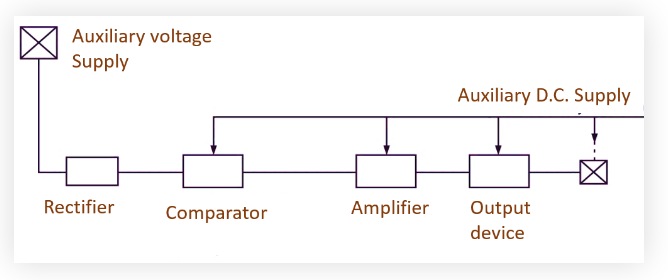
The static relay can generally be divided into the following major sections:
- Input Circuit (Signal Conditioning Unit)
- Measuring Unit (Comparator or Decision Circuit)
- Amplifier Circuit
- Output Circuit (Tripping Unit)
- Auxiliary Power Supply

2.2 Input Circuit (Transducer or Signal Conditioning Stage):
The input circuit is the interface between the power system and the relay’s internal electronics. Its function is to receive, scale down, and condition the electrical quantities from the system—such as current, voltage, or frequency—so that they can be safely processed by the low-power static components.
Key Components:
- Current Transformers (CTs): Reduce high system current to a small, measurable value (e.g., 1 A or 5 A).
- Potential Transformers (PTs): Step down high system voltage to a safe level (e.g., 110 V).
- Rectifiers: Convert AC signals to DC, when the relay requires DC operation.
- Filters: Eliminate unwanted noise or harmonics from the input signals.
- Attenuators or Resistors: Control voltage/current levels for the measuring circuit.
The output of the input circuit is a low-level analog voltage or current signal proportional to the system quantity under observation.
2.3 Measuring Unit (Comparator or Decision-Making Circuit)
This is the core section of the static relay where the actual protection decision is made. It continuously compares the input electrical quantity (e.g., line current) with a preset reference or threshold value.
Key Sub components:
- Comparators (Analog or Digital): Compare the input signal with the reference level.
- Operational Amplifiers (Op-Amps): Used for high-gain signal comparison or summation.
- Transistors or Logic Gates: Convert analog comparison results into digital ON/OFF decisions.
- Timers or Integrator: Introduce intentional delays for time-graded protection (for example, in time-overcurrent relays).
Working Concept:
If the measured signal exceeds the set threshold, the comparator output changes its state from “low” to “high” which acts as the trigger signal for further amplification and tripping.
If Vinput > Vreference then comparator output = 1 (Trip command initiated).
This ensures that the relay operates only under fault conditions, providing reliability and discrimination.
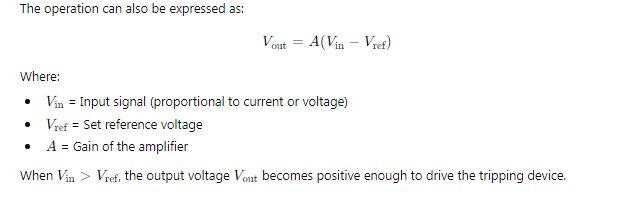
2.4 Amplifier Circuit:
Since the output signal from the comparator is usually of low power, it needs to be amplified to drive the tripping mechanism effectively.
Main Functions:
- Increase signal strength from millivolts or milliamps to levels suitable for actuating output relays.
- Isolate the sensitive measuring circuit from the power side of the output.
- Shape the output pulse (using transistor amplifiers or operational amplifiers).
Typical Devices:
- Transistor Amplifiers – Simple and fast amplification.
- Darlington Pair Transistors – Used where high current gain is required.
- Operational Amplifiers (Op-Amps) – Provide both voltage amplification and signal conditioning.
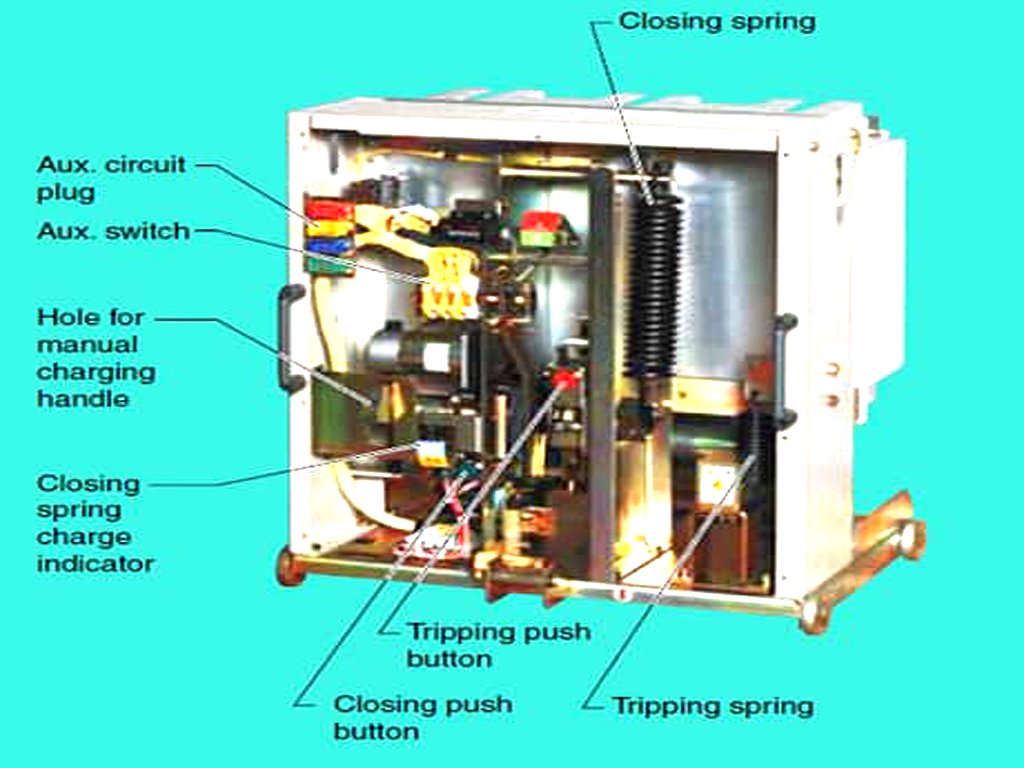
2.5 Output Circuit (Tripping Unit):
This stage provides the final switching action that energizes the trip coil of the circuit breaker. Although static relays are “non-moving” in their measurement sections, the final output often still uses an electromagnetic relay or solid-state switch to operate the breaker.
Output Device Options:
- Electromagnetic Relay (Auxiliary Output): Converts the electronic trip signal into a mechanical contact action.
- Silicon Controlled Rectifiers (SCRs): Allow rapid solid-state switching of trip circuits.
- Transistors or MOSFETs: Used in purely electronic trip outputs.
The tripping unit must be highly reliable and capable of handling the required DC trip current for circuit breaker operation.
2.6 Auxiliary Power Supply:
Static relays require a stable DC or regulated AC power supply to operate their electronic circuits. This supply is typically derived from:
- Station battery systems (e.g., 48 V, 110 V, or 220 V DC), or
- Internal conversion from the system voltage using rectifiers and regulators.
The power supply must ensure:
- Isolation from high-voltage transients.
- Low ripple for stable operation.
- Protection against polarity reversal or overvoltage.
2.7 Additional Supporting Elements:
Depending on the complexity of the protection scheme, static relays may also include:
- Logic circuits (AND, OR, NOT gates) for coordination between multiple inputs.
- Timers and time-delay networks for selective tripping.
- Memory circuits to hold operation signals.
- Reset circuits for automatic or manual resetting after tripping.
Working Principle of Static Relays:
The working principle of a static relay is based on electronic signal processing rather than the mechanical movement of components, as in electromagnetic relays.
It operates by comparing an electrical quantity (current, voltage, frequency, or phase angle) from the power system with a preset threshold or reference value. When this comparison indicates an abnormal or fault condition, the relay initiates a trip command to the circuit breaker to isolate the faulty section.
In simple terms:
> Static Relay = Measuring (Comparison) + Amplification + Tripping (Switching)
3.1 Basic Concept of Operation:
The fundamental operating sequence of a static relay involves three key stages:
- Signal Acquisition and Conditioning → Obtain analog signal (voltage/current) from the power system via CTs or PTs.
- Signal Comparison and Decision Making→ Compare the measured signal with a set reference to determine fault condition.
- Tripping Signal Generation → once fault is detected, amplify the signal and send it to trip the breaker.
3.1.1| Signal Acquisition and Conditioning
When a fault occurs in a power system (like a short circuit), there is a sudden change in voltage or current.
- For overcurrent protection, current through the line rises sharply.
- For undervoltage protection, the system voltage drops below normal.
This variation is captured by instrument transformers (CTs/PTs) and converted into small, proportional signals suitable for the relay.
The input circuit:
- Converts high-voltage/current signals to low levels.
- Filters out noise and harmonics.
- Rectifies AC to DC (if required).
- Produces a clean, measurable signal for further processing.
For instance:
If line current = 500 A, the CT might step it down to 5 A → then scaled further to a few mill amperes for internal circuits.
3.1.2: Signal Comparison and Decision Making:
The core logic of a static relay lies in its comparator or measuring circuit.
It continuously compares the incoming signal with a preset reference value, which represents the threshold between normal and fault conditions.
Example: Overcurrent Relay
Let:

This comparison is typically achieved using operational amplifiers configured as comparators.
When the input signal voltage exceeds the reference voltage at the comparator’s inverting or non-inverting terminal, the output changes from “0” (off) to “1” (on), triggering the next stage.
The comparator’s output is a low-level logic signal (typically in millivolts or milliamps).
This is insufficient to directly energize a circuit breaker trip coil, which usually requires several amperes of DC current.
Hence, the signal is sent to an amplifier stage, usually composed of transistors or operational amplifiers, to increase its power level.
The amplified signal is strong enough to drive:
- A power transistor, or
- A Silicon Controlled Rectifier (SCR)
which then energizes the trip coil or output relay.
3.1.3| Tripping Mechanism:
Once the amplified output signal is ready, it activates the tripping circuit.
Depending on relay design, this could happen in two ways:
- Electromechanical Output Stage:
The amplified signal energizes a miniature electromagnetic relay, which closes its contacts to complete the trip circuit of the circuit breaker.
- Fully Electronic Output Stage:
The amplified signal directly fires an SCR or triac, which passes DC current to the circuit breaker trip coil.
This arrangement is faster and has no mechanical delay.
After tripping, the system isolates the fault, and the relay resets either automatically or manually depending on its design.
Example of Static Overcurrent Relay Operation:
Step-by-Step Sequence:
- Input: Current signal from CT proportional to line current.
- Rectification: Signal converted to DC by a rectifier bridge.
- Filtering: Smoothing capacitor removes ripples from rectified signal.
- Reference Setting: A potentiometer sets the threshold current level.
- Comparison: Op-amp compares the filtered signal with the set reference.
- Amplification: If signal > reference, op-amp output goes high.
- Triggering: Output triggers an SCR, energizing trip coil.
- Tripping: Circuit breaker opens, isolating the faulty circuit.
The operation occurs within milliseconds, making static relays much faster than electromagnetic ones (which typically take tens of milliseconds to operate).
Time-Delayed Operation:
In many protection schemes (like time-overcurrent relays), operation is not instantaneous.
To achieve this, RC time-delay circuits (Resistor-Capacitor networks) are introduced in the comparator circuit.
- The RC circuit charges gradually when the input exceeds the threshold.
- Once the voltage across the capacitor reaches a trigger level, the comparator output changes state and initiates tripping.
- By adjusting R and C values, different time characteristics can be obtained (e.g., inverse-time, definite-time, etc.).
Operation under Fault and Normal Conditions:
| Condition | Input Signal Level | Relay Action | Output |
| Normal | Below threshold | Comparator output LOW | Trip coil de-energized |
| Fault | Above threshold | Comparator output HIGH | Trip coil energized – breaker opens |
This shows how static relays continuously monitor the system and react almost instantaneously when abnormal conditions arise.
Mathematical Representation:
Dynamic Performance:
Static relays are known for:
- High-speed response (operation within 10–30 ms).
- High sensitivity (accurate detection of small variations).
- Excellent repeatability, since no mechanical inertia is involved.+
Their reliability depends on stable power supply and robust circuit design, ensuring consistent operation even under noise and temperature variations.
Types of Static Relays:
Static relays can be classified in several ways depending on the quantity they measure, the function they perform, or the method of operation. Since their circuits can be designed for almost any protective characteristic, static relays are widely adaptable and versatile.
- Overcurrent Static Relays
- Undercurrent Static Relays
- Overvoltage and Undervoltage Static Relays
- Differential Static Relays
- Directional Static Relays
- Distance (Impedance) Static Relays
- Frequency Static Relays0
- Power and Reverse Power Static Relays
- Thermal Static Relays
- Phase Comparison Static Relays
Overcurrent Static Relays:
Definition:
An overcurrent static relay operates when the current through the relay exceeds a preset threshold value. It is one of the most commonly used static relays in distribution and transmission systems.
Working Principle:
- The input current from CTs is rectified and filtered.
- The DC signal is compared with a reference level representing the set current.
- When the signal exceeds the reference, the comparator activates a tripping signal.
Types:
- Instantaneous Overcurrent Relay: Trips immediately when the current exceeds the set value.
- Definite Time Overcurrent Relay: Trips after a preset time delay, even if current exceeds the set point. Time delay achieved using RC time constant circuits.
- Inverse Time Overcurrent Relay: Operating time decreases as current magnitude increases.
Applications: Used for protection of feeders, transformers, and distribution circuits.
Undercurrent Static Relays:
These relays operate when current falls below a certain limit.
They are used to detect open-circuit or underload conditions.
Working:
- A reference level is set using a zener diode or adjustable potentiometer.
- When the measured current is less than the threshold, output logic changes state and initiates tripping.
Applications:
- Motor protection against underload.
- Detection of line disconnection or phase loss.
Overvoltage and Undervoltage Static Relays:
Definition:
These relays respond to voltage variations beyond permissible limits.
Working Principle:
- Input voltage from PTs is rectified and filtered.
- Comparator checks voltage level against reference.
- Overvoltage relay operates when ( Vm > Vs ); undervoltage relay operates when ( Vm < Vs ).
Applications:
- Generator and busbar voltage protection.
- Motor protection from under/over voltage conditions.
Differential Static Relays:
Definition:
A differential static relay operates when the vector difference between two or more electrical quantities (currents or voltages) exceeds a preset limit.
Principle:
Idiff = |I1 – I2|
When Idiff ˃ Iset the relay trips.
Working:
- Input currents from two CTs on either side of the protected equipment are rectified and compared.
- The relay remains stable during external faults (equal currents), but operates during internal faults when the difference increases.
Applications:
- Transformer differential protection.
- Generator and busbar protection.
- Motor winding protection.
Directional Static Relays:
Definition:
Directional static relays determine the direction of power flow (or fault current) by comparing phase angles between voltage and current.
Working:
- The relay uses two input signals: one from the voltage circuit and another from the current circuit.
- These are processed through phase comparators (using cosine or sine phase angle detectors).
- If the phase angle between current and voltage corresponds to a reverse or forward direction fault, the relay issues a trip signal.
Types:
- Current-phase comparator
- Voltage-phase comparator
Applications:
- Directional overcurrent and power protection.
- Parallel generator operation (reverse power protection).
- Transmission line directional discrimination.
Distance (Impedance) Static Relays
Definition:
A distance relay operates when the impedance (Z = V/I) seen by the relay falls below a preset value, indicating a fault at a specific distance on the transmission line.
Working Principle:
- The relay receives both current and voltage signals.
- The ratio ( V/I ) is continuously monitored using electronic divider circuits.
- When measured impedance < set impedance, the relay operates.
Types of Distance Static Relays:
- Impedance Relay
- Reactance Relay
- Mho Relay
Each type has its own characteristic circle or line on the impedance (R–X) diagram.
Applications:
- Transmission line protection (phase and ground faults).
- High-voltage networks where fault location discrimination is needed.
Frequency Static Relays:
Definition:
Frequency relays detect deviations in system frequency from nominal (e.g., 50 Hz or 60 Hz).
Working:
- The input AC signal is fed into a frequency-to-voltage converter circuit.
- The resulting DC voltage is compared with reference levels representing high and low frequency limits.
- Overfrequency or underfrequency outputs are triggered accordingly.
Applications:
- Generator and turbine protection (load shedding control).
- System frequency stability maintenance.
Power and Reverse Power Static Relays
Definition:
Power relays measure the direction and magnitude of real or reactive power flow.
Working Principle:
- Voltage and current inputs are multiplied electronically to produce a signal proportional to power (P = VI cosΦ).
- Comparator checks the polarity of this signal to determine direction.
- A negative polarity indicates reverse power flow (e.g., when a generator starts motoring instead of generating).
Applications:
- Generator reverse power protection.
- Synchronization and interconnection protection.
Thermal Static Relays:
These relays protect equipment from overheating due to overcurrent or overload.
Working:
- The relay simulates heating by integrating current over time (I²t characteristic).
- Electronic integrator circuits (using capacitors and resistors) mimic the thermal behavior of windings.
- When “thermal level” exceeds threshold, relay trips.
Applications:
- Motor and transformer overload protection.
- Long-term thermal monitoring.
Phase Comparison Static Relays:
Definition:
Phase comparison relays compare the phase relationship between voltages or currents from two points in the system.
Working:
- Uses analog phase comparator circuits (multiplier or zero-crossing detectors).
- Operation occurs when the phase angle exceeds a defined limit, indicating internal fault.
Applications:
- Transmission line pilot protection schemes.
- Busbar differential protection.
Static Relays vs Electromagnetic Relays
Before the development of solid-state technology, electromagnetic relays were the standard protective devices in power systems. They relied on mechanical motion (of an armature, plunger, or disc) caused by electromagnetic forces to open or close contacts during faults.
With the advent of electronic components like diodes, transistors, operational amplifiers and integrated circuits, the static relay was introduced as a more efficient and reliable alternative.
The fundamental difference lies in how the operating signal is processed:
- Electromagnetic Relays: Operate through magnetic induction and mechanical movement.
- Static Relays: Operate through electronic signal processing without mechanical motion.
Constructional Differences
| Feature | Electromagnetic Relay | Static Relay |
| Main Components | Coils, iron core, moving disc, armature, contacts, springs | Resistors, capacitors, diodes, transistors, operational amplifiers, comparators |
| Mechanical Parts | Many moving parts (disc, lever, contacts) | No moving parts in measuring circuit |
| Output Mechanism | Electromagnetic movement closes contacts | Solid-state switching (may use an auxiliary electromagnetic trip) |
| Size & Weight | Bulky and heavy | Compact and lightweight |
| Power Consumption | High (due to coil energization) | Low (only for electronic circuits) |
Operational Differences:
| Parameter | Electromagnetic Relay | Static Relay |
| Operating Principle | Based on electromagnetic attraction or induction | Based on comparison of analog/digital signals |
| Response Time | Slow (20–50 ms) due to inertia | Fast (typically 10–20 ms or less) |
| Threshold Accuracy | Less accurate due to mechanical wear and friction | Highly accurate and stable (uses precise electronic reference) |
| Reset Time | Longer (mechanical movement must return to rest) | Shorter or instantaneous |
| Sensitivity | Moderate | Very high (can detect minute signal changes) |
| Repeatability | Affected by aging, dust, and temperature | Highly repeatable due to solid-state circuits |
| Vibration Impact | Sensitive to vibration and shock | Immune to vibration and mechanical wear |
In short: Static relays are faster, more sensitive, and more precise than electromagnetic relays.
Functional and Performance Differences:
| Aspect | Electromagnetic Relay | Static Relay |
| Power Source Dependency | Operates directly from system current/voltage | Requires auxiliary DC supply |
| Contact Wear | Contacts carry current and wear out over time | No contacts in measuring part (only in tripping output) |
| Burden on CT/PT | High | Very low (reduces CT/PT loading) |
| Temperature Effect | Coil resistance changes with temperature | Slight drift in electronic components (can be compensated) |
| Temperature Effect | Coil resistance changes with temperature | Slight drift in electronic components (can be compensated) |
| Maintenance | Frequent (cleaning, calibration, lubrication) | Minimal (periodic testing only) |
| Reliability | Mechanical fatigue possible | Long life, high reliability |
| Testing & Setting | Done mechanically by adjusting springs or air gaps | Done electrically using potentiometers or digital settings |
Speed of Operation Differences:
Electromagnetic Relays:
Operation time depends on mechanical movement, friction, and electromagnetic induction lag. Average tripping time is 20–50 ms.
Static Relays:
Since they use purely electronic circuits, their operation time is typically 10–20 ms or less, providing faster system clearance and improving power system stability.
This fast action is critical in high-voltage transmission networks, where fault clearance time directly affects transient stability.
Sensitivity and Accuracy Differences:
Electromagnetic relays rely on magnetic forces to move components, which can vary due to wear, vibration, or magnetic saturation. Static relays, however, use voltage comparators and precise electronic references, which:
- Offer constant performance over time,
- Maintain stable pickup values, and
- Are not affected by mechanical drift.
Thus, static relays can detect smaller faults earlier and provide more reliable discrimination between healthy and faulty zones.
Maintenance and Reliability Differences:
Electromagnetic Relays: Require regular maintenance because moving parts may wear, corrode, or lose calibration.
Static Relays: No moving parts → less wear → longer life span.
Static relays, however, need protection against surge voltages, dust, and temperature extremes, which could damage semiconductor components.
Economic Comparison:
Initially, static relays were more expensive due to the cost of electronic components. However, with mass production and technological advances, they became cost-effective and cheaper to maintain than electromagnetic relays.
| Cost Aspect | Electromagnetic Relay | Static Relay |
| Initial Cost | Low to moderate | Moderate to high |
| Maintenance Cost | High (mechanical servicing) | Very low |
| Life Span | Shorter due to wear | Longer (no mechanical parts) |
| Overall Cost Over Time | Higher | Lower |
Advantages of Static Relays:
Static relays marked a revolutionary improvement in protection engineering by replacing the moving mechanical components of electromagnetic relays with solid-state electronic circuits. This shift brought a wide range of technical, operational, and economic advantages that greatly enhanced system reliability, speed, and precision.
- High Speed of Operation: they can operate almost instantaneously, typically within 10–20 milliseconds or even faster.
- High Sensitivity: Sense small fault currents in high-impedance networks and Respond to weak signals even when input energy is minimal.
- Excellent Accuracy and Repeatability: Their pickup and reset values are highly accurate and repeatable. There is no variation due to friction, wear, or temperature drift as seen in electromagnetic relays. The relay characteristics remain consistent throughout their life.
- No Mechanical Inertia or Contact Bounce: Because static relays have no moving parts in their measuring section, they are free from problems like: Mechanical inertia (which delays response), Contact bounce (which causes unreliable operation), Wear and tear due to vibration or movement.
- High Reliability and Long Life: The absence of mechanical components and use of solid-state devices means that static relays- Have longer operational life and less affected by mechanical shock or vibration. Require minimal maintenance compared to traditional relays.
- Low Power Consumption and Burden: Static relays draw very little energy from the measuring transformers (CTs/PTs). Their burden is typically less than 1 VA, while electromagnetic relays can draw 10–20 VA or more.
- Compact Size and Lightweight Design: Because they use miniature solid-state components (like diodes, transistors, and ICs), static relays are much smaller and lighter than electromagnetic ones.
- Flexible and Complex Characteristics: Unlike electromagnetic relays, whose characteristics are fixed by mechanical design, static relays can easily be modified or customized by adjusting circuit parameters like resistors or capacitors. This flexibility allows: Creation of any desired operating characteristic, such as definite-time, inverse-time, or exponential time curves. Implementation of logical combinations (AND, OR, NOT) for coordinated tripping. Integration of multiple protection functions in a single device.
- Stable Operation and Wide Range of Application: Static relays provide stable operation even under varying environmental and system conditions. They are: Not affected by vibration or mechanical shocks, Stable over wide temperature ranges** (with proper compensation), and Immune to mechanical drift and dust-related issues.
- Lower Maintenance Requirements: Electromagnetic relays require routine maintenance such as: Contact cleaning, Lubrication of moving parts, Checking of springs and armature tension, etc, Static relays, on the other hand: Have no moving parts, so wear and tear is virtually zero. Require only periodic functional testing and visual inspection. Offer high reliability even in remote or unattended substations.
- Fast Reset and Reclose Capability: Since static relays operate electronically, they can reset almost instantly after fault clearance. This is essential for automatic reclosing in transmission systems, where reclosing needs to occur within fractions of a second after transient fault clearance. Electromagnetic relays, by contrast, may require several seconds to reset due to the mechanical inertia of moving parts.
- Easy Coordination and Adjustability: Static relays have precise and easily adjustable settings using potentiometers, switches, or even dip selectors. This allows: Fine-tuning for system coordination, Reconfiguration of protection zones without changing hardware, Easy testing and calibration in the field, For instance, inverse-time overcurrent relays can have adjustable time multipliers and current settings with high resolution and repeatability.
Disadvantages of Static Relays:
Despite their many advantages, static relays are not free from drawbacks. Their dependence on electronic components and auxiliary DC supply, along with sensitivity to environmental conditions, makes them somewhat vulnerable compared to modern microprocessor-based relays.
- Susceptibility to Electrical Noise and Transients: Static relays use semiconductor devices that can be affected by: Electromagnetic interference (EMI), Radio-frequency interference (RFI), Switching surges, Lightning-induced transients, or High-frequency oscillations on transmission lines. Such disturbances may cause: Spurious operation (false tripping), or Failure to operate when required.
- Dependence on Auxiliary DC Supply: Static relays typically require a continuous auxiliary DC supply (e.g., 24V, 48V, 110V, or 220V DC) for their internal circuits. If this supply fails: The relay becomes completely inoperative, No protection is available and Even monitoring circuits may shut down.
- Temperature Sensitivity: Semiconductor components like transistors, diodes and op-amps are sensitive to temperature changes.
- At high ambient temperatures: Leakage currents increase, Biasing points shift and Operating thresholds may drift. Although compensation techniques (like temperature-stable zener diodes) are used, performance still degrades outside the specified temperature range (usually –10°C to +55°C). Thus, static relays require temperature control or air-conditioned enclosures in some installations.
- Limited Overload Capability: Unlike electromagnetic relays that can withstand short bursts of high current or voltage, static relays are less tolerant to overloads or surges. Semiconductors can be damaged permanently by: Voltage spikes, Overcurrent, or Power surges. Hence, protective devices like fuses, surge arresters and filters must be added, increasing the circuit’s complexity and cost.
- Complexity of Circuit Design: Static relays are based on combinations of electronic components — amplifiers, comparators, rectifiers, timers, SCRs etc. This introduces: Complex design and manufacturing, Difficulty in fault diagnosis and Need for skilled maintenance technicians familiar with electronic circuits. In contrast, the operation of an electromagnetic relay is easily understood and tested by visual inspection.
- Limited Field Repair and Maintenance: If a static relay fails, it often requires replacement of electronic components or entire circuit modules. These repairs: Need trained personnel and diagnostic tools (oscilloscopes, multimeters, etc.), Cannot be done easily on-site, and May require sending the unit back to the manufacturer. Electromagnetic relays, on the other hand, could often be repaired in the field by replacing contacts or cleaning parts.
- Aging and Component Drift: With time, electronic components like resistors, capacitors, and transistors may experience parameter drift, such as: Changes in resistance or capacitance, Shift in reference voltage levels, or Deterioration due to aging. This drift can affect calibration accuracy and relay characteristics, requiring periodic testing and recalibration to maintain reliability.
- Vulnerability to Humidity and Dust: Moisture, condensation and dust can create leakage paths and cause short circuits across closely spaced electronic components. This can: Disturb circuit operation, Lead to false tripping or Permanently damage sensitive devices. Therefore, static relays must be housed in dustproof, moisture-resistant enclosures and preferably installed in controlled environments.
- Initial Cost and Complexity: When static relays were first introduced, their initial cost was relatively high due to the price of semiconductor devices and the need for high-quality auxiliary supplies. Although their long-term cost is lower, utilities initially found it more expensive to replace all electromagnetic relays with static types. Moreover, special testing equipment was often required, further increasing setup costs.
- Possibility of False Operation:Because static relays respond quickly to input variations, they may misinterpret transient disturbances (like inrush currents or switching surges) as actual faults if not properly filtered. To prevent this, designers include: Stabilizing circuits,Time delay filters andLogic discrimination. But these additions complicate the design and slightly increase response time.
- Limited Self-Checking Ability: Traditional static relays do not have built-in self-diagnostic or self-checking features. If an internal circuit fails, the relay may remain inoperative without any external indication. In contrast, modern numerical relays (microprocessor-based) continuously monitor their health and can alert operators to internal failures. Thus, static relays lack the intelligent monitoring found in newer technology.
Applications of Static Relays
Static relays are deployed across the entire power system—from generation to distribution—to ensure system stability, equipment protection, and high-speed fault clearance. Their use is crucial in areas where fast action and precise measurement are paramount.
- High and Extra High Voltage (EHV/UHV) Transmission Line Protection
This is perhaps the most critical application where static relays demonstrate their superiority.
- High-Speed Distance Protection: Static relays are the standard choice for distance protection (e.g., Mho relays, Quadrilateral relays) on EHV and UHV transmission lines. Their ability to measure the line impedance (Z = V/I) and respond in a few milliseconds is vital for maintaining system transient stability following a major fault.
- Phase Comparison Schemes: They are used in advanced phase comparison and segregated phase comparison schemes for unit protection of long transmission lines, offering high-speed and secure tripping.
- Traveling Wave Relays: The fastest protective relays in existence are based on static or digital technology, using the detection of traveling waves generated by a fault to clear the fault in less than one millisecond, further pushing the boundaries of system protection.
- Generator Protection
Generators are the most valuable and crucial assets in a power plant, requiring multi-layered, high-sensitivity protection.
- Differential Protection: Static relays are used in longitudinal differential schemes for windings, where they compare the current entering and leaving the winding to instantly detect internal faults (like short circuits or turn-to-turn faults). The high sensitivity of static relays allows detection of minor insulation failures.
- Loss-of-Excitation (40) Relays: Used to detect the loss of field current, which can lead to the generator operating asynchronously. Static relays provide precise detection of the generator impedance moving into the unstable zone.
- Reverse Power (32) Relays: Protect against motoring of the generator (when it draws power from the grid instead of supplying it).
- Transformer Protection
Power transformers are protected using static relays for both internal and external faults.
- Restrained Differential Protection (87T): High-speed static differential relays are essential here. They utilize a harmonic restraint feature (due to their electronic nature) to differentiate between a severe internal fault and the inrush current that occurs when a transformer is energized, preventing false tripping.
- Overcurrent and Earth Fault Protection: Used as backup protection and for external faults.
- Busbar Protection
Busbars are critical nodes in a substation. A fault on a busbar affects multiple circuits, making fast clearing paramount.
- High-Impedance Differential Protection: Static relays provide very fast, secure, and sensitive protection for the bus zone, minimizing damage and ensuring quick system restoration.
- Motor and Industrial Systems Protection
In large industrial motors, static relays offer precise control and protection.
- Thermal Overload Protection: Static relays can closely model the thermal heating and cooling curve of a motor, providing more accurate and sensitive overload protection than simple current monitoring.
- Phase Imbalance and Phase Sequence: Used to detect voltage or current imbalance between phases, which is highly destructive to three-phase motors.
- Power Quality and System Stability
Static relays are fundamental in monitoring and responding to system-wide conditions.
- Under/Over Frequency (81) Relays: Essential for load shedding When the system frequency drops due to generation deficit, static frequency relays quickly identify the condition and selectively trip non-critical loads to restore the frequency balance.
- Under/Over Voltage (27/59) Relays: Used to protect sensitive equipment from voltage excursions and to implement system voltage control schemes.
- Automation and Control
While their primary role is protection, the inherent electronic nature of static devices lends them well to control applications.
- Solid-State Relays (SSRs): Simple static devices used for high-speed, high-cycle switching applications in industrial control systems where the contacts of an EMR would wear out quickly.
The high speed and customizable characteristics achievable with electronic circuits are what make static relays the preferred technology for almost all critical protection functions in a modern power grid.