Definition of Supervisory Control and Data Acquisition (SCADA):
SCADA (Supervisory Control and Data Acquisition) is a system architecture comprising computers, networked data communications, and graphical user interfaces for high-level supervision of machines and processes, as well as an interface to lower-level control devices like PLCs (Programmable Logic Controllers) and RTUs (Remote Terminal Units) for data acquisition and local control.
It is an industrial control system used to monitor, control and automate processes such as power generation, water treatment, manufacturing, oil and gas production, and many other industrial operations.
In simple terms, SCADA allows operators to observe real-time data, control equipment remotely and analyze system performance through computers and communication networks.
Key Functions of SCADA:
- Data Acquisition – Collecting data from sensors, instruments, and field devices.
- Data Communication – Transmitting data between remote field sites and the control center.
- Data Presentation – Displaying data in graphical or tabular form to operators (e.g., dashboards, alarms).
- Control – Sending control commands (like open/close valves, start/stop motors) to field devices.
- Data Storage and Analysis – Recording historical data for performance evaluation and fault analysis.
History of SCADA:
- Early Automation (Before 1960s):
- Before SCADA, manual monitoring and control were common.
- Operators physically checked instruments and manually adjusted valves or switches.
- First Generation – Monolithic SCADA (1960s–1970s):
- Early SCADA systems were standalone and based on mainframe computers.
- Communication was proprietary, meaning systems from different manufacturers couldn’t easily connect.
- Used mostly in electric utilities and oil refineries.
- Second Generation – Distributed SCADA (1980s):
- Introduction of Local Area Networks (LANs).
- Tasks like data collection, processing and control were distributed across multiple computers.
- Improved reliability and flexibility.
- Third Generation – Networked SCADA (1990s):
- Development of wide-area networking (WAN) allowed remote monitoring over large geographical areas.
- Open protocols (like Modbus, DNP3) were introduced for easier integration between different systems.
- SCADA began to use client-server architecture.
- Fourth Generation – Internet-Based SCADA (2000s–Present):
- Integration with Internet, cloud computing, and IoT (Internet of Things).
- Use of web-based HMIs, wireless communication and cybersecurity measures.
- Modern SCADA systems now provide real-time analytics, mobile access and AI-driven decision support.
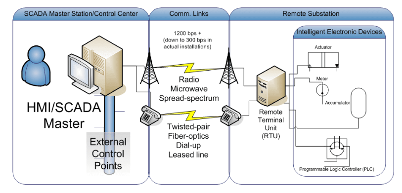
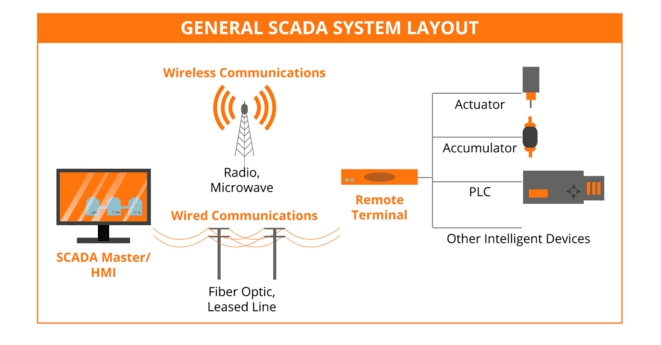
Basic Components of a SCADA System:
- Human-Machine Interface (HMI) – The user interface where operators monitor and control processes.
- Supervisory System – Central computer that processes data and issues control commands.
- Remote Terminal Units (RTUs) – Devices that collect data from sensors and send it to the SCADA master.
- Programmable Logic Controllers (PLCs) – Used for local control and automation.
- Communication Network – Enables data transfer between central control and remote devices.
- Sensors and Actuators – Measure physical quantities (like pressure, flow, voltage) and execute control actions.
Explanation:
- Human-Machine Interface (HMI): This is the graphical interface and software that allows human operators to view system data, monitor the process status, and issue control commands. It acts as the operator’s window into the process.
- Supervisory System (Master Terminal Unit – MTU): This is the central server and software responsible for communicating with the field controllers (RTUs/PLCs), aggregating data, and running analysis, hosting the HMI, and sending supervisory control commands. It’s the “brain” of the SCADA system.
- Remote Terminal Units (RTUs) and Programmable Logic Controllers (PLCs): These are microprocessor-based devices deployed in the field (remote locations or a factory floor).
- RTUs are optimized for remote locations and communicate telemetry data back to the MTU.
- PLCs are robust industrial computers commonly used for high-speed, local control in manufacturing settings.
- Both act as local collection points for sensor data and execute control commands from the supervisory system.
- Communication Infrastructure: This network system connects the supervisory system (MTU/HMI) with the remote terminal units (RTUs/PLCs) and field devices. It uses a mix of wired (Ethernet, fiber optic) and wireless (radio, cellular) technologies to ensure reliable, real-time data transfer.
- Field Devices (Sensors & Actuators): These are often considered the foundational layer of the system. These are the devices that interface directly with the physical process. Sensors measure process variables like temperature, pressure, or flow rate. Actuators receive control signals (from RTUs/PLCs) and perform physical actions, such as opening a valve or starting a motor.
Control and Visualization of Power Plant Data through SCADA Systems
SCADA (Supervisory Control and Data Acquisition) is an industrial automation system used to monitor and control field devices from a central location. It integrates hardware and software to collect data from sensors, transmit it to control centers, and allow operators to visualize, analyze, and control plant processes.
In modern power plants, reliable operation and continuous monitoring are essential to ensure efficiency, safety, and stability. Supervisory Control and Data Acquisition (SCADA) systems play a crucial role in achieving these goals by providing centralized control, real-time data visualization, and automated decision-making support.
Functions of SCADA in Power Plants:
- Real-Time Monitoring: Tracks generator output, transformer status, bus voltage, current, frequency, etc.
- Remote Control: Enables operators to start/stop equipment, change set points, and isolate faults.
- Data Logging and Archiving: Stores historical data for performance analysis and fault diagnosis.
- Alarm Management: Alerts operators to abnormal conditions or equipment failures.
- Visualization: Displays plant data on graphical user interfaces (GUIs), mimicking the real system layout.
- Reporting: Generates reports on power generation, efficiency, and operational trends.
Control in SCADA Systems:
a) Supervisory Control:
Operators can control power plant processes from a central control room by:
- Sending commands to open/close circuit breakers.
- Regulating generator excitation voltage and turbine speed.
- Controlling cooling systems, feedwater pumps, and boiler temperature.
b) Automatic Control (Closed-Loop):
SCADA often integrates with Programmable Logic Controllers (PLCs) or Distributed Control Systems (DCS) for automated control:
- Automatically adjusts plant parameters based on sensor feedback.
- Maintains stable generation under varying loads.
- Provides protection and interlocking to prevent unsafe operations.
c) Remote Control:
- Enables control from distant stations through communication networks.
- Common in grid control centers managing multiple power plants.
Data Collection in SCADA Systems:
a) Process Data Acquisition:
- Sensors measure parameters such as voltage, current, power factor, pressure, temperature and flow.
- Analog data (continuous signals) are converted into digital form using Analog-to-Digital Converters (ADCs).
b) Data Transmission:
- Data are transmitted through wired or wireless networks using protocols like Modbus, DNP3, or IEC 60870-5-104.
- Communication occurs between field devices (RTUs/PLCs) and the Master Station (SCADA server).
c) Data Processing and Storage:
The SCADA Master Station collects data, filters noise, and stores it in databases for trend analysis, fault detection, and reporting.
Visualization and Monitoring
- HMI Display: The HMI translates complex data into user-friendly graphical interfaces, allowing operators to see the current state of the entire power plant and transmission network at a glance.
- Alarm Management: The SCADA system constantly monitors parameters against thresholds, automatically generating alerts on the HMI (audible and visual) when critical limits are reached (e.g., high transformer temperature or low frequency), enabling swift operator response.
Visualization allows operators to see the status and performance of the entire power plant in real time:
- Mimic Diagrams: Graphical representations of the plant (boilers, turbines, transformers, switchyards, etc.) showing live data.
- Trend Displays: Historical and real-time trends of voltage, frequency, and power output.
- Alarm Dashboards: Highlight fault areas or abnormal parameters.
- Energy Reports: Summaries of generation efficiency, losses, and downtime.
Visualization improves situational awareness and enables quick corrective action.
Power Plant SCADA Components and Functions:
| Component | Function |
| 1. Sensors & Transducers | Measure physical parameters (voltage, current, temperature, pressure, etc.) and convert them into electrical signals. |
| 2. Remote Terminal Unit (RTU) | Collects data from sensors, performs basic control, and communicates with the master station. |
| 3. Programmable Logic Controller (PLC) | Executes logical control operations and handles automation tasks locally; often used instead of RTUs in modern systems. |
| 4. Communication Network | Transmits data between field devices and the control center; may use Ethernet, fiber optics, radio, or satellite links. |
| 5. Master Terminal Unit (MTU) / Central Server | Acts as the main controller; collects data from multiple RTUs/PLCs and issues commands to them. |
| 6. Human–Machine Interface (HMI) | Graphical interface for operators to visualize real-time processes, alarms, and trends; allows manual control. |
| 7. Database / Historian Server | Stores real-time and historical data for performance analysis, optimization, and reporting. |
| 8. Alarm and Event System | Notifies operators of faults or abnormal conditions using audio-visual alerts. |
| 9. Engineering Workstation | Used for configuration, system programming, and maintenance of the SCADA system. |
Advantages of SCADA in Power Plants:
- Centralized monitoring and control of complex processes.
- Reduced manpower requirements.
- Enhanced reliability and faster fault detection.
- Improved efficiency through data-driven operation.
- Better safety via alarms and automated shutdowns.
- Easy integration with smart grid systems.
How to Displaying Generator Terminal Voltage in a SCADA System:
Displaying the generator terminal voltage in a Supervisory Control and Data Acquisition (SCADA) system is a multi-step process that converts a high-voltage physical signal into a digital value displayed on the operator’s Human-Machine Interface (HMI).1
Steps for Data Acquisition and Visualization
Measurement at the Generator:
- The high terminal voltage (e.g., 2$13.8$ kV) is measured using Potential Transformers (PTs), also known as Voltage Transformers (VTs).3
- The PTs step down the high voltage to a standardized, safe, low-voltage analog signal (e.g., 120V AC or less) suitable for protection relays and measuring instruments.
Transducer/Protection Relay Interface:
- The stepped-down AC signal is fed into a Transducer or a Multifunction Protection Relay (IED – Intelligent Electronic Device).4
- The transducer converts the AC analog signal (120V) into a standardized DC analog signal (e.g., 4-20mA or 0-10V) or, more commonly in modern systems, the IED digitizes the voltage measurement directly.
Field Controller (RTU/PLC) Integration:
- The digitized voltage data from the IED or the analog signal from the transducer is wired to an Analog Input (AI) module on a Remote Terminal Unit (RTU) or a Programmable Logic Controller (PLC).5
- The RTU/PLC then reads this value and performs the necessary scaling and engineering unit conversion (e.g., converting the 4-20mA signal back into the actual terminal voltage, like 13.8 kV).
Communication to the Supervisory System:
- The RTU/PLC uses a standard industrial communication protocol (like Modbus, DNP3, or IEC 61850) to transmit the scaled, real-time voltage data (a data point or SCADA tag) to the central Master Terminal Unit (MTU) or SCADA Server.
HMI Visualization:
- The SCADA software running on the MTU receives the data tag.
- The HMI designer links this data tag to a visual object on the screen, such as a digital display, an analog meter graphic, or a trend chart located on the generator’s mimic diagram. The operator sees the real-time voltage (e.g., 13.75 kV) displayed in its correct engineering units.
Applications of SCADA in Power Systems:
SCADA systems are used across the entire power generation, transmission, and distribution network. Below are key applications:
In Power Generation Plants:
- Monitoring and control of generators, turbines, and boilers.
- Regulation of voltage, frequency, and power output.
- Monitoring of cooling systems, pumps, and fans.
- Load management and synchronization.
- Automatic startup/shutdown sequences.
- Alarm and event handling for equipment protection**
In Power Transmission Systems:
- Monitoring transmission line parameters: voltage, current, power factor, frequency etc.
- Control of circuit breakers and isolators remotely.
- Fault detection, isolation, and service restoration.
- Line overload and temperature monitoring.
- Supervision of substations and remote switching.
In Power Distribution Systems:
- Remote control of feeders and transformers.
- Load shedding and demand-side management.
- Monitoring power quality (voltage sags, swells and harmonics).
- Integration with smart meters and distribution automation.
- Energy management and real-time loss analysis.
Industrial and Utility Applications:
- Hydroelectric plants: Monitoring water level, gate position, turbine output.
- Thermal power plants: Monitoring steam pressure, boiler temperature, fuel feed rate.
- Renewable energy systems: Monitoring solar panel output or wind turbine generation.
- Utility control centers: Centralized monitoring of multiple substations or power stations.
SCADA systems are the backbone of modern power plant automation.
Through efficient control, accurate data collection, and advanced visualization, they ensure that power plants operate safely, efficiently, and reliably — meeting the growing demands of modern power networks.
SCADA for Power Transmission System:
The power transmission system transports large quantities of electricity over long distances from generating stations to substations.
Because these networks are vast and geographically dispersed, SCADA (Supervisory Control and Data Acquisition) systems are essential for real-time monitoring, control, and protection of the grid.
Objectives of SCADA in Transmission:
- Monitor high-voltage lines, transformers, and substations.
- Control circuit breakers, isolators, and tap changers remotely.
- Detect and isolate faults to minimize outage duration.
- Collect operational data (voltage, current, power factor, frequency).
- Enhance grid reliability and stability.
c) Key Functions:
- Real-Time Monitoring
- Voltage, current, frequency, power flow, and line load.
- Transformer status, oil temperature, and gas pressure.
- Supervisory Control
- Remote operation of circuit breakers, isolators, and capacitor banks.
- Tap changer adjustments for voltage regulation.
- Fault Detection and Isolation
- Detects overvoltage, under voltage and line faults.
- Isolates faulty sections automatically through protection logic.
- Event Logging and Alarms
- Records faults, switching events and alarms for analysis.
- Data Communication:
- Uses protocols like IEC 60870-5-104, DNP3, or Modbus TCP/IP for data exchange between substations and the control center.
Components in Transmission SCADA:
| Component | Function |
| RTU (Remote Terminal Unit) | Installed at substations to collect field data and execute control commands. |
| Sensors and Transducers | Measure current, voltage, and temperature. |
| Communication Network | Transfers data between substations and the control center (fiber optics, microwave and satellite). |
| Master Station (Control Center) | Centralized location for monitoring and control of multiple substations. |
| HMI (Human–Machine Interface) | Displays real-time one-line diagrams of the transmission network. |
Advantages:
- Real-time visibility of grid conditions.
- Rapid fault detection and isolation.
- Reduced downtime and improved reliability.
- Optimized power flow and voltage regulation.
- Enhanced coordination between substations and generation plants.
SCADA for Power Distribution System
The power distribution system delivers electricity from substations to end consumers (industrial, commercial, and residential).
With the increasing demand for reliability and efficiency, SCADA systems are used for distribution automation — making the network smarter, faster, and more flexible.
Objectives of SCADA in Distribution:
- Monitor and control feeders, distribution transformers, and switchgear.
- Minimize power outages and quickly restore supply.
- Improve power quality and reduce energy losses.
- Integrate with smart grid and Advanced Metering Infrastructure (AMI).
Key Functions:
- Feeder Monitoring and Control
- Monitors voltage, current, and load on distribution feeders.
- Controls circuit breakers, reclosers, and sectionalizers.
- Fault Location, Isolation and Service Restoration (FLISR)
- Automatically detects faulted segments, isolates them, and restores power to healthy sections.
- Load Management:
Performs load balancing and demand-side management.
- Voltage Regulation and Power Factor Correction.
- Controls capacitor banks and on-load tap changers.
- Energy Accounting and Theft Detection
- Collects data from smart meters for billing and loss reduction.
- Integration with Renewable Energy
- Monitors distributed generation sources like solar panels and wind turbines.
Components in Distribution SCADA:
| Component | Function |
| Feeder RTUs / PLCs | Installed at distribution substations and along feeders for data acquisition and control. |
| Sensors and Transducers | Measure voltage, current, power, and energy usage. |
| Communication Infrastructure | Utilizes fiber optics, cellular or radio for data transfer. |
| SCADA Master Station | Centralized monitoring of multiple feeders and substations. |
| HMI / GIS Integration | Provides geographical and schematic visualization of the network. |
Advantages of Distribution SCADA:
- Faster fault detection and automatic power restoration.
- Improved reliability and power quality.
- Reduced technical and non-technical losses.
- Efficient energy management and load control.
- Enables Smart Grid and Demand Response capabilities.
Transmission SCADA ensures stable, safe and reliable operation of high-voltage networks by providing real-time control and fault management.
Distribution SCADA enhances service reliability, enables automation, and integrates renewable and smart grid technologies.
Together, they form the backbone of a digitally controlled power system, from generation to end-user delivery.
Advantages of SCADA:
- Real-Time Monitoring and Control
- SCADA continuously monitors system parameters such as voltage, current, temperature, pressure, or flow rate.
- Operators can instantly detect changes and take corrective action through the control interface.
- Improved System Efficiency:
- Automatic control and optimization reduce energy waste and operational losses.
- Helps maintain stable and efficient process conditions (e.g., voltage regulation, load balancing).
- Reduced Manpower and Operational Cost:
- Remote operation reduces the need for manual supervision in the field.
- One control center can manage multiple plants or substations.
- Faster Fault Detection and Restoration:
- Faults are detected in real time with alarm notifications.
- Quick isolation and restoration minimize downtime and equipment damage.
- Historical Data Logging and Analysis:
- SCADA systems store operational data for performance review, trend analysis, and predictive maintenance.
- Helps identify inefficiencies or recurring issues.
- Enhanced Safety and Reliability:
- Automatically triggers protective actions (e.g., shutdowns or isolation) when unsafe conditions occur.
- Ensures operator and equipment safety.
- Scalability and Flexibility:
- SCADA systems can easily integrate new devices, control zones, or automation modules.
- Compatible with advanced systems like IoT (Internet of Things) and smart grids.
- Remote Accessibility:
- Operators can monitor and control systems from remote locations via secure networks.
- Particularly useful for geographically distributed assets like transmission lines or pipelines.
- Improved Decision-Making:
- Real-time data, visual dashboards, and reports support faster, data-driven operational decisions.
Relation between SCADA and Industrial Automation:
a) Understanding Industrial Automation:
Industrial Automation refers to the use of control systems — such as PLCs, DCS, and robots — to operate industrial processes with minimal human intervention. Its main goal is to improve productivity, accuracy, safety, and reliability.
b) Role of SCADA in Industrial Automation:
SCADA acts as the supervisory layer in industrial automation.
While PLCs or DCS units perform local control at the process level, SCADA oversees and coordinates them at a higher level by collecting, visualizing, and managing data.
c) Relationship Explained:
| Aspect | Industrial Automation | SCADA System |
| Function | Automates individual machines or processes using PLCs, sensors and actuators. | Supervises and controls multiple automated systems from a central location. |
| Control Level | Local (machine-level control) | Supervisory (plant-wide or multi-site control) |
| Components | PLCs, sensors, actuators, drives | RTUs/PLCs, communication networks, servers, HMIs |
| Data Flow | Device → PLC | PLC/RTU → SCADA Master Station |
| Visualization | Limited or none | Full graphical interface (HMI) for monitoring |
| Example | A PLC controls a pump or motor automatically | SCADA monitors multiple pumps, displays flow rates, and logs data |
d) How They Work Together
- Sensors measure process variables (temperature, pressure, voltage, etc.).
- PLCs or RTUs control equipment based on logic or setpoints.
- SCADA collects data from all PLCs/RTUs through communication networks.
- Operators use the SCADA interface to monitor, analyze, and modify operations in real time.
Example:
- In a power plant, a PLC controls the turbine’s speed and steam valve.
- The SCADA system displays generator voltage, turbine speed and alarms, allowing operators to adjust parameters or stop the system if needed.
e) Integration Benefits:
- Unified control of entire industrial processes.
- Centralized data storage and analysis.
- Improved process visibility and coordination.
- Easier troubleshooting and maintenance.
- Supports Industry 4.0 and Smart Factory concepts.