AC circuits in electrical engineering, understanding power in AC (Alternating Current) systems is crucial for designing, operating, and maintaining efficient electrical networks. Unlike DC circuits —where power calculations are straightforward as the product of voltage and current—in AC circuits, the situation is more complex due to the phase difference between voltage and current caused by reactive elements like inductors and capacitors.
To properly describe and analyze AC power, engineers divide total power into three components: active power, reactive power and apparent power. These three quantities are interrelated through what is known as the power triangle, and their relationship is governed by the power factor, a measure of how effectively electrical power is converted into useful work.
Understanding Power in AC Circuits
In an AC circuits, both voltage and current vary sinusoidally with time. For example, a voltage can be represented as:
v(t) = Vm sin(ωt)
and the current as:
i(t) = Im sin(ωt – Ø)
Here:
- Vm and Im are the maximum (peak) values of voltage and current,
- ω is the angular frequency,
- Ø is the phase angle between voltage and current.
The instantaneous power is given by:
p(t) = v(t) x i(t)
Expanding this:
p(t) = Vm Im sin(ωt) sin(ωt – Ø)
Active Power (Real Power):
Definition:
Active power, also known as real power or true power, is the portion of total power that actually performs useful work in a circuits. It is measured in watts (W). Symbol is P, Unit is Watt (W) or Kilowatt (kW). It’s the beer in a mug of beer and foam—the part you can actually drink.

Mathematically:
P = Vrms Irms cosØ
Where:
- Vrms = RMS voltage,
- Irms = RMS current,
- cos(Ø ) = power factor (PF).
Explanation:
Active power represents the energy that is converted into other forms—mechanical work, heat, or light. For example:
- In an electric motor, it produces mechanical rotation.
- In a heater, it generates heat.
- In a lamp, it produces light.
Characteristics:
- It depends on both the magnitude of voltage and current and the cosine of the phase angle.
- It is the only part of power that represents useful energy consumption.
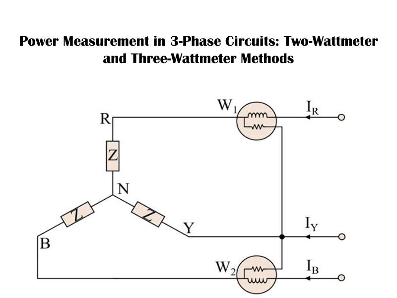
- It is measured by wattmeter in AC circuits.
Reactive Power:
Definition:
Reactive power is the portion of total power that oscillates back and forth between the source and the reactive components (inductors and capacitors) in the circuits. It is measured in volt-ampere reactive (VAR).
Mathematically:
Q = VrmsIrmssin(Ø)
Explanation:
Reactive power does not perform any useful work. Instead, it sustains the electric and magnetic fields in inductive and capacitive components. In other words, it represents the energy alternately stored and released per cycle in the magnetic or electric field.
Examples:
- In an inductor, reactive power is used to establish a magnetic field.
- In a capacitor, reactive power is used to establish an electric field.
Characteristics:
- It is essential for the operation of AC equipment (like motors and transformers) but does not do useful work.
- It can cause voltage drops and losses in the power system if not properly managed.
- It can be leading (capacitive) or lagging (inductive) depending on the circuits nature.
Apparent Power:
Definition:
Apparent power is the total power flowing from the source to the load, combining both active and reactive power. It is measured in volt-ampere (VA).
Mathematically:
S = Vrms Irms
And its relationship with real and reactive power is:
S2 = P2 + Q2
Explanation:
Apparent power represents the total power that must be supplied by the source to cover both the useful (active) and useless (reactive) components. It indicates the total current-carrying requirement of the system.
Characteristics:
- Apparent power determines the rating of generators, transformers, and transmission equipment.
- It is the vector sum (not algebraic) of active and reactive power.
The Power Triangle:
To visualize the relationship between active, reactive, and apparent power, engineers use the power triangle.
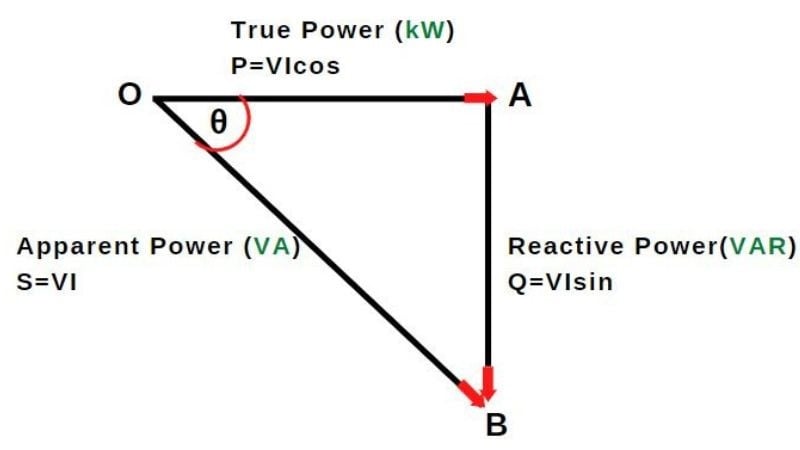
In this triangle:
- The horizontal axis represents Active Power (P),
- The vertical axis represents Reactive Power (Q),
- The hypotenuse represents Apparent Power (S).
tan(Ø) = Q/P
And therefore:
cos(Ø) = P/S
Here, (Ø) is the phase angle between voltage and current.
Interpretation of the Power Triangle:
- For inductive loads (motors, transformers), current lags voltage, and (Q) is positive (lagging power factor).
- For capacitive loads, current leads voltage, and (Q) is negative (leading power factor).
- The smaller the phase angle (Ø), the closer the apparent power is to real power, indicating better efficiency.
The Role of Power Factor (PF):
The Power Factor (PF) is one of the most critical metrics in an AC system, as it indicates how effectively electrical power is being converted into useful work.
- Definition: The power factor is the cosine of the phase angle (Ø) between the voltage and current, or equivalently, the ratio of Active Power to Apparent Power.
- Calculation:
PF = cos(Ø) = Active Power (P) / Apparent Power (S)
- Ideal Value: The ideal power factor is 1.0$ (or unity). This means the phase angle Ø is 0° and the reactive power (Q) is zero. In this case, P=S, and all the apparent power delivered is doing useful work.
Nature of the Load:
- Resistive Load (e.g., heater): PF = 1 (Unity)
- Inductive Load (e.g., motor, transformer) : PF is Lagging (Current lags the voltage, Ø > 0° .This is the most common low PF issue.
- Capacitive Load (e.g., capacitor bank): PF is Leading (Current leads the voltage, Ø< 0°).
Importance of Power Factor in Power Systems:
A low power factor indicates that a larger portion of the current contributes to reactive power rather than real power. This has several technical and economic consequences.
Increased Line Losses:
When power factor decreases, the current in the circuits increases for the same active power. Since line losses are proportional to ( I2R ) more current means higher losses.
Losses ∝ I2 R
Larger Equipment Size:
Transformers, alternators, and transmission lines must be rated for apparent power (S), not real power (P). A lower power factor means the same real power requires larger apparent power, leading to bulkier, more expensive equipment.
Voltage Regulation Issues:
Low power factor causes higher voltage drops across transmission lines and feeders, leading to poor voltage regulation and unstable operation.
Reduced System Efficiency:
Because a low power factor increases current flow and losses, it reduces the overall efficiency of the power system.
Penalties from Utilities:
Electric utility companies often impose penalties for industrial customers with low power factor because it increases the reactive power burden on the grid. Maintaining a high power factor avoids such penalties.
Methods of Power Factor Improvement:
Improving power factor is essential for efficient and cost-effective operation. Some common methods include:
(a) Capacitor Banks:
Installing shunt capacitors across inductive loads provides leading reactive power to neutralize lagging reactive power from inductors.
(b) Synchronous Condensers:
An over-excited synchronous motor running without load can supply reactive power, improving system power factor.
(c) Phase Advancers:
Used in induction motors, phase advancers provide the magnetizing current required, thus reducing lagging reactive current drawn from the supply.
(d) Static VAR Compensators (SVC):
These are power electronic devices that dynamically adjust reactive power compensation in high-voltage networks.
Example Calculation
Let’s consider a practical example:
A 3-phase motor takes a current of 40 A at 400 V and a power factor of 0.8 lagging.
P = √3 V x I cos (ф)
P = 1.732x 400 x40x 0.8 = 22.18 kW,
Apparent power:
S = √3 V x I = 1.732 x 400 x 40 = 27.71 kVA
Reactive power:
Q = √ (S2 – P2 )= √ {(27.71)2 – (22.18)2 } = 16.60 KVAR
Hence:
- Active Power (P): 22.18 kW
- Reactive Power (Q): 16.6 kVAR
- Apparent Power (S): 27.71 kVA
- Power Factor (cosφ): 0.8 lagging
If the power factor is improved to 0.95, the reactive power reduces significantly, improving efficiency and reducing current draw.
- Real-World Significance:
- In Industrial Systems: Most industrial machines are inductive (motors, welders, transformers), which cause lagging power factor. Power factor correction devices are therefore essential to maintain efficiency.
- In Power Transmission: Utilities use compensating devices to keep power factor close to unity, reducing losses and improving voltage stability.
- In Renewable Energy Systems: Inverters in solar and wind systems are designed to maintain near-unity power factor for grid stability.