Switchgear:
In the realm of electrical engineering, switchgear is a crucial component of any power system, encompassing a range of devices designed to control, protect, and isolate electrical equipment. Think of it as the central nervous system of an electrical network, ensuring the safe and reliable distribution of electricity.
The apparatus used for switching, controlling and protecting the electrical circuits and equipment is known as switchgear.
At its core, switchgear is a collection of switching and protective devices such as switches, fuses, and circuit breakers, housed together in a metal enclosure. Its primary functions are to:
- Control: To energize or de-energize a part of the electrical system.
- Protect: To interrupt the flow of current when a fault, such as a short circuit or overload, is detected, thereby preventing damage to equipment and ensuring the safety of personnel
- Isolate: To provide a clear and visible break in the circuit, allowing for safe maintenance and repair work to be carried out on downstream equipment.
A typical switchgear assembly includes a combination of the following key components:
- Circuit Breakers: Devices that can automatically interrupt high fault currents and can be reset after the fault is cleared.
- Fuses: Sacrificial devices that contain a thin wire designed to melt and break the circuit if the current exceeds a safe level.
- Switches: Devices used to manually open or close a circuit.
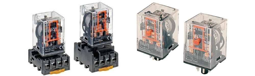
- Relays: The “brains” of the protective system, which detect abnormal conditions and send a signal to the circuit breaker to trip.
- Isolators (Disconnectors): Switches that provide a visible break in the circuit to ensure it is de-energized for maintenance.
- Busbars: Metallic bars or tubes that conduct electricity from the incoming supply to the various outgoing circuits.
- Transformers: Instrument transformers (current and potential transformers) are used to step down high currents and voltages to safe levels for measurement and for the operation of protective relays.
Here’s a detailed look at some of the key components that make up a switchgear assembly:
Air Break Switch
An Air Break Switch is a type of switch that uses air as the dielectric medium to extinguish the arc that is generated when the switch’s contacts are opened to interrupt the flow of current. When the contacts separate, an arc is formed between them. This arc is then elongated and cooled by the surrounding air, eventually extinguishing it and breaking the circuit. These switches are typically used in outdoor, medium-voltage applications.
Isolator
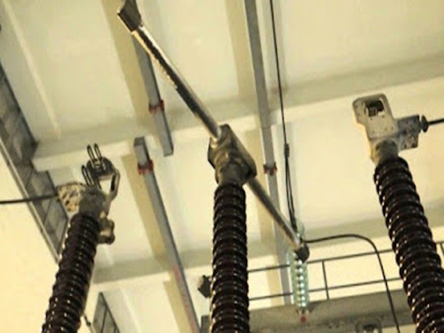
An isolator, or disconnector, is a mechanical switch used to ensure that an electrical circuit is completely de-energized for service or maintenance. A key feature of an isolator is the visible break it provides in the circuit, offering a clear visual confirmation that the circuit is open and safe to work on. It’s important to note that isolators are operated under no-load conditions, meaning the current must be interrupted by another device, like a circuit breaker, before the isolator is opened.
Oil Switch
An oil switch is a type of switch where the contacts are submerged in insulating oil. The oil serves two primary purposes: it insulates the live parts from each other and from the earthed container, and it helps to extinguish the arc that forms when the circuit is interrupted. The oil cools the arc and the hydrogen gas produced from the decomposition of the oil helps to de-ionize the arc path, leading to its extinction.
Fuse
A fuse is one of the simplest and most common forms of overcurrent protection. It consists of a thin metal wire or strip that is designed to melt and “blow” when the current flowing through it exceeds a certain level for a specific duration. By melting, the fuse creates a break in the circuit, stopping the flow of excessive current and protecting the connected equipment. Once a fuse has blown, it must be replaced.
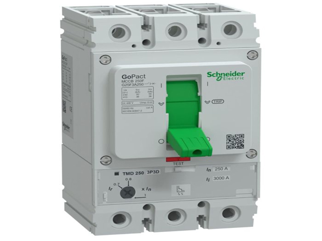
Circuit Breaker
A circuit breaker is an automatic switching device that can interrupt an electrical circuit under both normal and fault conditions. Unlike a fuse, a circuit breaker can be reset (either manually or automatically) to resume normal operation after a fault has been cleared. Circuit breakers are essential for the protection of electrical systems from overloads and short circuits. They come in various types, classified by the medium used for arc extinction, such as:
- Air Circuit Breakers (ACB): Use air at atmospheric pressure to extinguish the arc.
- Oil Circuit Breakers (OCB): Use insulating oil as the arc quenching medium.
- Vacuum Circuit Breakers (VCB): The arc is extinguished in a vacuum.
- Sulphur Hexafluoride (SF6) Circuit Breakers: Utilize the high dielectric strength of SF6 gas to quench the arc.
Relays
A relay is a sensing device that detects a fault in an electrical system and initiates the operation of the circuit breaker to isolate the faulty part. Relays are the “brains” of the protection system. They continuously monitor electrical quantities like current, voltage, and frequency. When these quantities deviate from their preset limits, the relay sends a trip signal to the circuit breaker. There are many types of relays, each designed to detect specific types of faults, such as overcurrent relays, distance relays, and differential relays.
Busbar
A busbar is a metallic strip or bar, typically made of copper or aluminum that is used to conduct electricity within a switchgear assembly, substation, or other electrical apparatus. It acts as a central distribution point for electrical current. In a switchgear panel, busbars connect the incoming power to the various outgoing feeder circuits, each of which is protected by a circuit breaker or fuse.
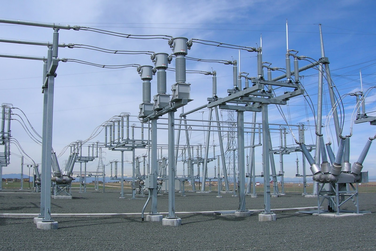
Instrument transformers:
Instrument transformers are a specialized class of transformers used in AC power systems to safely measure high levels of voltage and current. They scale down these high values to a standardized, low, and safe level that can be easily handled by standard measuring instruments, meters, and protective relays.
Here are two main types of instrument transformers: Current Transformers (CTs) and Potential Transformers (PTs), also known as Voltage Transformers (VTs).
Current Transformer (CT)
A Current Transformer (CT) is an instrument transformer designed to produce an alternating current in its secondary winding which is proportional to the alternating current being measured in its primary winding. Essentially, it’s a “current-stepping-down” device.
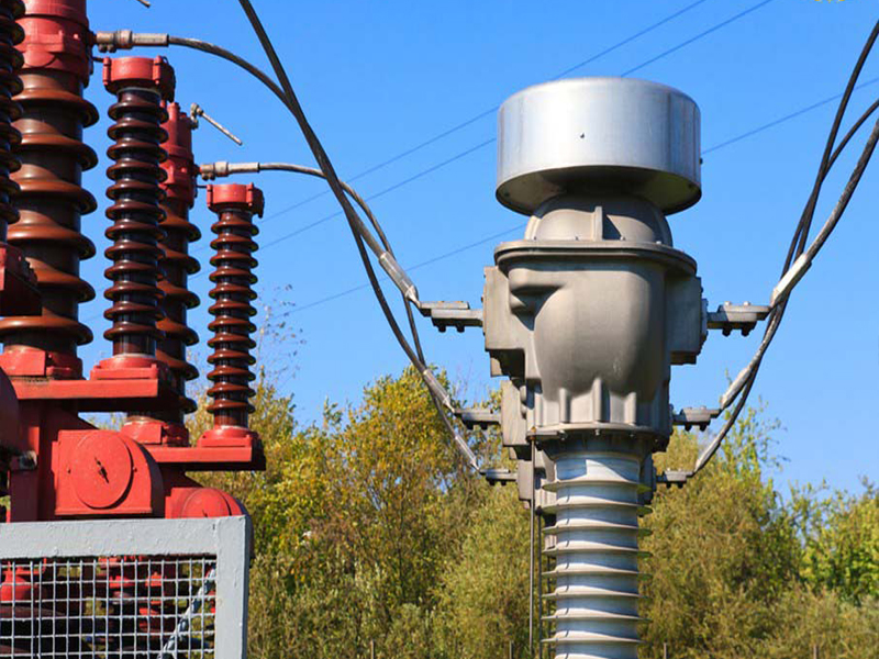
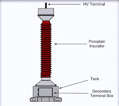
Potential Transformer (PT) or Voltage Transformer (VT)
A Potential Transformer (PT), also commonly called a Voltage Transformer (VT), is used to step down high system voltages to a lower, safer value for measurement and protection purposes.
Busbar Arrangements:
A busbar arrangement, also known as a bus scheme, is the specific design and connection of busbars within an electrical substation or switchgear assembly. A busbar is a metallic bar or strip that acts as a central junction to collect electrical power from incoming feeders and distribute it to outgoing feeders.
The way these busbars are configured is critical because it directly impacts the substation’s operational flexibility, reliability, and ease of maintenance. The goal is to choose an arrangement that balances cost, safety, and continuity of service for the specific application.
Common Busbar Arrangements
Here are some of the most common busbar arrangements, each with its own set of advantages and disadvantages.
1. Single Busbar Arrangement
This is the simplest and most economical arrangement. All incoming and outgoing circuits are connected to a single common busbar.
Advantages:
- Low initial cost.
- Simple design and easy operation.
- Requires less space.
Disadvantages:
- Low Reliability: A fault on the busbar itself will cause a complete shutdown of the entire substation.
- Difficult Maintenance: The entire busbar must be de-energized to perform maintenance on any section of it, resulting in a complete power outage.
2. Single Busbar with Bus Sectionalizer
This is an improvement on the single bus scheme where the busbar is divided into two or more sections, connected by a circuit breaker and isolators.
Advantages:
- Improved Reliability: A fault on one section of the bus can be isolated, allowing the other section to remain in service.
- Easier Maintenance: One section can be de-energized for maintenance while the other half continues to supply power.
Disadvantages:
- Slightly higher cost than the simple single bus arrangement.
- If the sectionalizing breaker fails, it can still cause a major outage.
3. Main and Transfer Bus Arrangement
This scheme adds a second bus, called the “transfer bus,” alongside the main bus. A bus coupler (a circuit breaker and isolators) connects the two buses. Each circuit has isolators allowing it to be connected to either the main or the transfer bus.
Advantages:
- Excellent Maintenance Flexibility: Any circuit breaker can be taken out of service for maintenance by transferring its load to the transfer bus via the bus coupler. This ensures continuity of power.
- The cost is lower than more complex double busbar schemes.
Disadvantages:
- A fault on the main busbar will still cause a complete shutdown of all circuits connected to it.
- Switching operations can be complex.
4. Double Busbar, Double Breaker Arrangement
This is a highly reliable but expensive configuration. It features two main buses, and every circuit is connected to both buses using two dedicated circuit breakers.
Advantages:
- Maximum Reliability and Flexibility: Any circuit can be fed from either bus, and any breaker can be removed for maintenance without interrupting the circuit’s power supply. Busbar maintenance can also be done without causing an outage.
- No interruption of service during a busbar fault.
Disadvantages:
- Very High Cost: It is the most expensive arrangement due to the requirement of two circuit breakers for each circuit.
- Requires a larger physical footprint.
5. Breaker-and-a-Half Arrangement
This advanced scheme uses three circuit breakers in series to connect two circuits to two main buses. As the name implies, it uses 1.5 breakers per circuit on average. It is commonly used in high-voltage substations where reliability is paramount.
Advantages:
- High Reliability: A fault on either bus will not interrupt service to any circuit.
- Any circuit breaker can be maintained without interrupting the power supply.
Disadvantages:
- High cost.
- The relaying and control schemes are more complex.
6. Ring Bus Arrangement
In this configuration, the circuit breakers are arranged in a closed loop or ring, with circuits connected between the breakers.
Advantages:
- Economical and reliable, offering two paths for power to each circuit.
- Any single circuit breaker can be taken out of service without interrupting any load.
Disadvantages:
- If a fault occurs, the ring is split, which can lead to overloading of the remaining lines.
- Adding new circuits to the ring can be difficult and may require a complete shutdown.
Important Terms:
Arc Voltage:
- It is the voltage that appears across the separating contacts of a circuit breaker during the period when an electrical arc is established and maintained.
- This voltage is generally low, but it rises rapidly to a peak value near the point of current zero.
- The arc voltage helps to sustain the arc, which must be quickly extinguished for a successful interruption.
Restriking Voltage (or Transient Recovery Voltage – TRV):
- It is the transient voltage that appears across the circuit breaker contacts immediately after the arc is extinguished at or near a natural current zero.
- This voltage is a high-frequency, damped oscillatory transient caused by the sudden distribution of energy between the magnetic field (inductance) and electric field (capacitance) of the system.
- It is called “restriking voltage” because its rapid rise determines whether the arc will re-ignite (restrike) across the contact gap before the dielectric strength of the medium (like oil or gas) can build up sufficiently. The Rate of Rise of Restriking Voltage (RRRV) is a crucial factor in circuit breaker design.
Recovery Voltage:
- It is the normal frequency (e.g., 50 Hz or 60 Hz) root mean square (RMS) voltage that appears across the circuit breaker contacts after the final arc extinction and after all high-frequency transients (like the restriking voltage) have completely died out.
- It is essentially the steady-state system voltage (phase-to-neutral voltage) and represents the normal voltage that the open contacts must continuously withstand to ensure the circuit remains interrupted.