What is a Polyphase System?
A polyphase system is a means of distributing alternating-current (AC) electrical power that utilizes two or more energized electrical conductors carrying alternating currents with a defined phase difference between the voltage waves in each conductor. While systems with various numbers of phases exist, the three-phase system is the most common and is used almost universally for power distribution. In a balanced three-phase system, the three voltage or current waves are of the same frequency and amplitude but are out of phase with each other by 120 degrees or 2π/3 radians.
The primary advantages of a three-phase system over a single-phase system include:
- More Efficient Power Transmission: A three-phase system can transmit three times as much power as a single-phase system using only 1.5 times the number of conductors, making it significantly more economical.
- Constant Power Delivery: The total instantaneous power in a balanced three-phase system is constant, unlike the pulsating power of a single-phase system. This results in smoother operation of machinery.
- Self-Starting Motors: Three-phase induction motors are self-starting due to the rotating magnetic field produced by the three-phase supply, simplifying their construction and improving reliability.
Phase Sequence and Naming
Phase Sequence:
Phase sequence is the order in which the voltages in the different phases reach their maximum positive values. For a three-phase system, there are two possible phase sequences.
- Positive Sequence: This is the standard sequence, often denoted as R-Y-B, A-B-C, or 1-2-3. In this sequence, the voltage in phase R reaches its peak first, followed by the voltage in phase Y after 120 degrees, and then the voltage in phase B after another 120 degrees. This can be visualized as a clockwise rotation of the phasors.
- Negative Sequence: This is the reverse sequence, denoted as R-B-Y, A-C-B, or 1-3-2. Here, the voltage in phase R is followed by phase B and then phase Y. This corresponds to a counter-clockwise rotation of the phasors.
The direction of rotation of a three-phase motor is dependent on the phase sequence. Reversing the phase sequence, which can be done by swapping any two of the three line conductors, will reverse the motor’s direction of rotation.
Naming
Naming the phases is done through standardized conventions. The most common nomenclatures are:
- R, Y, B: Representing Red, Yellow, and Blue, which historically corresponded to the insulation colors of the wires.
- A, B, C: A common alphabetical designation.
- 1, 2, 3: A numerical designation.Double Subscript Notation
Double subscript notation
Double subscript notation is a method used to clearly define the direction of voltage and current in AC circuits, particularly in polyphase systems. It helps to avoid ambiguity
- For Voltage (e.g. VAB)
This represents the voltage at point A with respect to point B. The first subscript (A) denotes the point of higher potential during the positive half-cycle of the voltage wave. Thus,
VAB=−VBA
- For Current (e.g. IAB)
This represents the current flowing from point A to point B. The direction of positive current flow is from the first subscript to the second. Therefore,
IAB=−IBA
This notation is especially useful when analyzing star and delta connected systems, as it clarifies the relationship between phase and line quantities.
Interconnection of Three Phases
In a three phase system, the three individual phase windings of a generator or a load can be interconnected in two primary ways. This interconnection reduces the number of conductors required from six (two for each phase) to three or four. In three phase electrical systems, the windings of transformers, generators, and motors can be connected in one of two primary configurations: star (also known as wye or Y) and delta (also known as mesh or Δ). Each connection method has distinct characteristics that make it suitable for different applications.
Star or Wye (Y) Connection
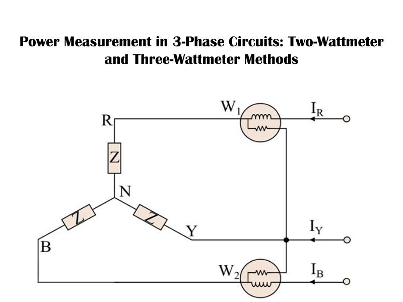
In a star or wye connection, one end of each of the three phase windings is connected to a common point, known as the neutral or star point. The other ends of the windings are connected to the line conductors.
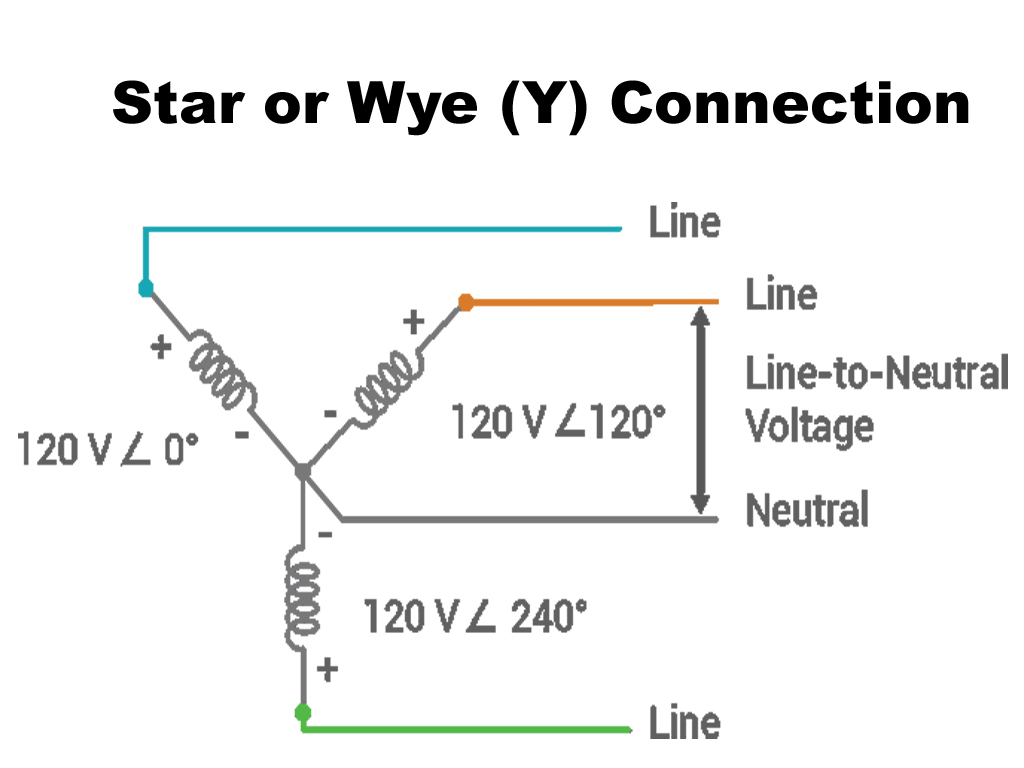
- Configuration: The connection resembles the letter ‘Y’. A fourth wire, the neutral wire, can be brought out from the neutral point, creating a three phase, four-wire system. If the neutral wire is not used, it is a three phase, three-wire system.
- Voltage and Current Relationship:
The line current ( IL) is equal to the phase current ( Iph)
IL = Iph
* The line voltage VL= 3×Vph
The line voltages are displaced from their corresponding phase voltages by 30 degrees.
- Applications: The star connection is commonly used in both power transmission and distribution networks as it allows for two different voltage levels (line-to-line and line-to-neutral), making it suitable for supplying both three phase and single-phase loads.
Mesh or Delta (Δ) Connection
In a mesh or delta connection, the three phase windings are connected in series to form a closed loop, resembling the Greek letter delta (Δ). The three line conductors are taken from the three junctions of the closed mesh.
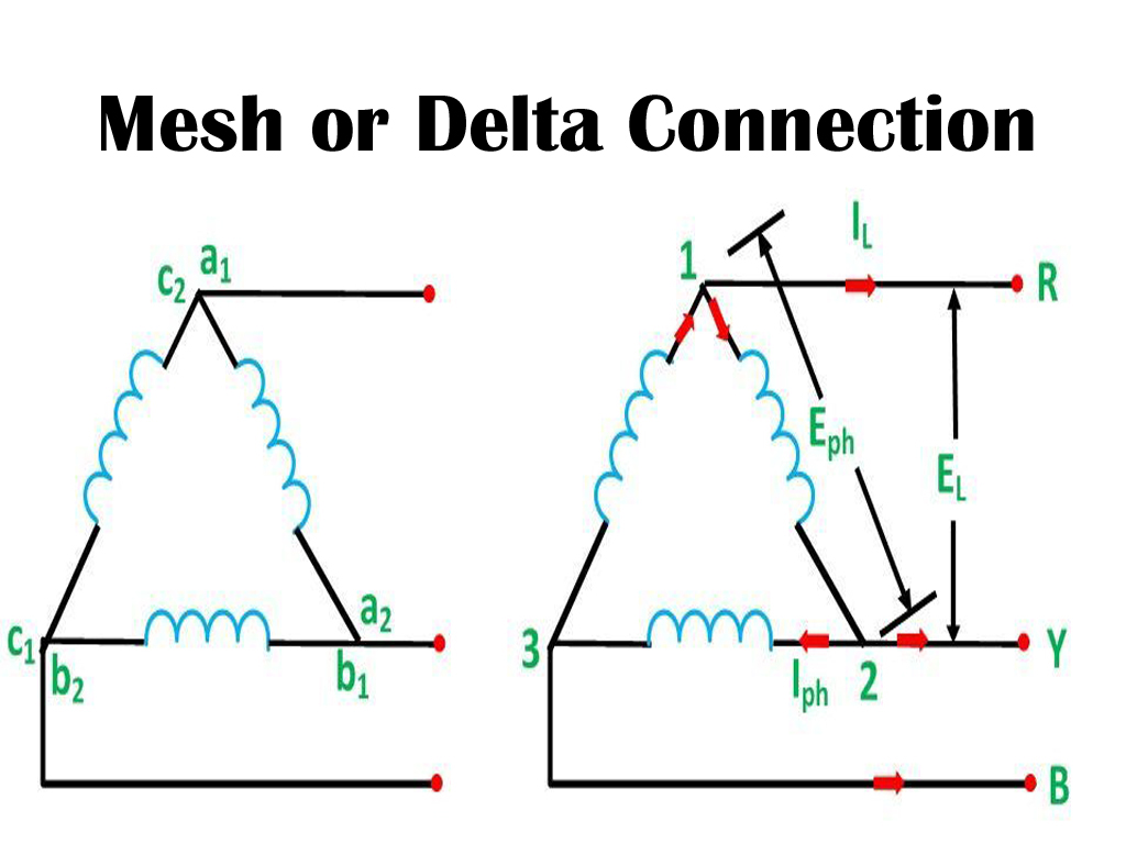
- Configuration: This connection forms a closed triangular loop. There is no neutral point in a delta connection, so it is always a three-phase, three-wire system.
- Voltage and Current Relationship:
The line voltage ( VL) is equal to the phase voltage ( Vph): VL = Vph
The line current ( IL) is sqrt of 3 times the phase current ( Iph): IL = 3×Iph
The line currents are displaced from their corresponding phase currents by 30 degrees.
- Applications: Delta connections are often used in industrial applications with high starting torque requirements and for shorter distance power distribution. A key advantage is that if one winding of a delta-connected transformer bank fails, the remaining two can continue to supply three-phase power in an “open delta” configuration, albeit at a reduced capacity.
Advantages of Star Connection
- Availability of Neutral Point: The most significant advantage is the presence of a neutral point. This allows for two different voltage levels: the line-to-neutral voltage (phase voltage) and the line-to-line voltage (line voltage). This makes it ideal for distribution systems where single-phase loads (like residential lighting and appliances) and three-phase loads (like industrial motors) are to be supplied from the same source.
- Lower Insulation Requirement: In a star connection, the voltage across each phase winding is lower than the line-to-line voltage by a factor of 3 (specifically, Vph = VL/3). This means the windings require less insulation, making the equipment more cost-effective.
- Earth Grounding: The neutral point provides a convenient location for grounding the system. Grounding improves safety by providing a path for fault currents and helps in protecting equipment from voltage surges.
- Reduced Phase Current: While the line current is equal to the phase current ( IL=Iph), the lower phase voltage means that for a given power rating, the phase current can be lower compared to a delta system with a higher phase voltage.
- Suitable for Unbalanced Loads: The presence of a neutral wire provides a return path for current in the case of unbalanced loads, helping to maintain a more stable voltage across the different phases.
Disadvantages of Star Connection
- Lower Starting Torque: For a given line voltage, the lower phase voltage in a star-connected motor results in a lower starting torque compared to a delta-connected motor.
- Third Harmonic Issues: In some cases, the third harmonic currents can be a problem as they are in phase with each other and can lead to a large current flowing in the neutral wire if one is present.
Delta (Mesh) Connection
In a delta connection, the three windings are connected end-to-end, forming a closed triangular loop. The line conductors are connected at the three junctions of this loop.
Advantages of Delta Connection
- Higher Starting Torque: Since the phase voltage is equal to the line voltage ( Vph=VL), motors connected in delta produce a higher starting torque, which is beneficial for heavy industrial loads.
- No Neutral Point Required: The three-wire system is simpler and may be more economical in terms of wiring for applications that do not require a neutral connection.
- Reliability in Transformer Banks (Open Delta): If one winding of a delta-connected transformer bank fails, the remaining two windings can continue to supply three-phase power in what is known as an “open delta” or “V” connection. The capacity is reduced to about 58% of the original bank, but it allows for continuity of service until repairs can be made.
- Circulation of Third Harmonics: In a delta connection, the third harmonic currents, which are in phase, circulate within the closed loop of the delta. This prevents them from flowing into the line conductors and causing interference with communication systems.
- Higher Power Output: For the same winding specification, a delta connection can deliver a higher power output as the line current is 3 times the phase current ( IL=3Iph) at a full line voltage.
Disadvantages of Delta Connection
- No Neutral Point: The absence of a neutral point means it can only supply a single, higher three-phase voltage. It is not suitable for mixed-load environments that require both single-phase and three-phase power at different voltage levels.
- Higher Insulation Requirement: Because the phase voltage is equal to the line voltage, the windings must be insulated for the full line voltage, which can increase the cost.
- Difficulty with Unbalanced Loads: Delta systems are less effective at handling unbalanced loads, which can lead to significant voltage variations across the phases.
- Higher Phase Current: For a given power and voltage, the phase current in a delta winding is higher than in a star winding.