What is Relays ?
- Relay is a device by means of which an electric circuit is controlled by the change in the same circuit or other circuit.
- The protective relays
- Sense the abnormal conditions in a part of the power system.
- Give an alarm and isolate faulty part from the healthy system.
In the realm of electrical power systems, protective relays are important devices that detect abnormal conditions and initiate corrective actions, primarily by tripping a circuit breaker to isolate the faulty section. This ensures the safety of equipment and personnel, and maintains the stability of the overall system. These relays can be broadly categorized based on their function, operating principle, and characteristics. Two fundamental operating characteristics that define the time-current response of overcurrent relays are Definite Minimum Time (DMT) and Inverse Definite Minimum Time (IDMT).
Basic Concepts of Different Types of Relays
Protective relays can be classified in several ways:
Protective Relay:
- Over Current Relay (50/51)
- Earth Fault Relay (50N/51N)
- Directional Relay (67)
- Differential Relay (87) :
- Distance Relay (21)
- Frequency Relay (81)
- Over Flux Relay (24)
Non-Protective Relay:
- Circuit Breaker Relay (52)
- Isolator Relay (89)
- Lockout Relay (86)
- Auto Reclosing Relay (79)
- Synchronizing Relay (25)
By Technology:
Electromechanical Relays:
These are the traditional type of relays that operate based on the magnetic and mechanical forces generated by the fault current. They are robust but have slower operating times and are less precise than modern relays.
Fundamental Operating Principle
The operation of an electromechanical relay is based on a simple yet effective concept:
- Energizing the Coil: A current, typically from a current or potential transformer that senses the state of the power system, flows through a coil of wire wound around a ferrous core.
- Creating a Magnetic Field: This current generates a magnetic field. Under normal operating conditions, this magnetic field is relatively weak.
- Attracting the Armature: When a fault occurs (like a short circuit), the current dramatically increases. This surge creates a powerful magnetic field strong enough to overcome a restraining force (usually a spring) and attract a movable iron component called an armature.
- Closing the Contacts: The movement of the armature is mechanically linked to a set of contacts. As the armature moves, it forces these contacts to close.
- Tripping the Circuit Breaker: The closing of the relay contacts completes a separate trip circuit, which in turn energizes the trip coil of a circuit breaker. The circuit breaker then opens, isolating the faulty part of the electrical system.
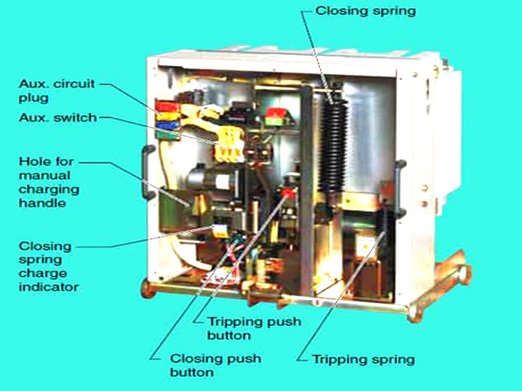
Core Components
Every electromechanical relay, regardless of its specific type, consists of these fundamental parts:
- Electromagnet: This is the “brain” of the relay, comprising a wire coil and an iron core. It converts the electrical fault signal into a magnetic force.
- Armature: The moving part of the relay, typically made of iron, that is attracted by the magnetic field.
- Contacts: These are the electrical switch elements. They can be:
- Normally Open (NO): The contacts are open in the non-operated state and close when the relay operates.
- Normally Closed (NC): The contacts are closed in the non-operated state and open when the relay operates.
- Springs: These provide the restraining force, holding the armature in its normal position and ensuring the relay resets after the fault is cleared and the coil is de-energized.
- Frame/Housing: The structure that holds all the components together and provides protection from the environment.
Types of Electromechanical Relays
While the underlying principle is similar, electromechanical relays were developed in several forms to suit different applications:
1. Attracted Armature Type Relays
This is the simplest and most common type. The magnetic force produced by the coil directly attracts the armature to operate the contacts. They are known for their fast operation. Sub-types include:
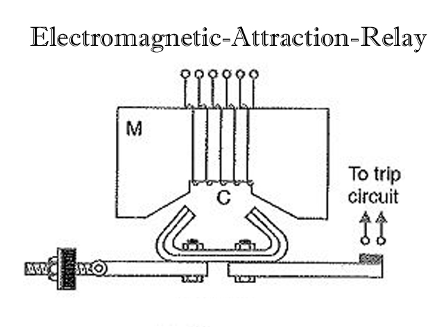
- Hinged Armature: The armature is pivoted and moves in an angular fashion.
- Plunger (Solenoid) Type: A plunger is drawn into the center of a coil (solenoid).
- Balanced Beam Type: An armature is balanced on a pivot between two coils (one operating, one restraining), used to compare two electrical quantities.
Application: Widely used for overcurrent and overvoltage protection, as well as auxiliary functions in control circuits.
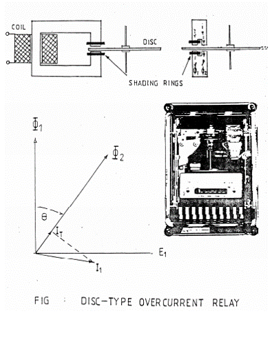
2. Induction Type Relays
These relays operate on the principle of an induction motor and are used exclusively for AC systems. The torque is produced by the interaction of two alternating magnetic fluxes that are displaced in time and space.

- Induction Disc Type: An aluminum disc is free to rotate between the poles of two electromagnets. Eddy currents induced in the disc by one magnet’s flux interact with the flux of the other magnet, creating a rotational torque. The speed of rotation, and thus the operating time, is inversely proportional to the current (providing an IDMT characteristic).
- Induction Cup Type: A variation that uses a hollow cylindrical cup as the rotor, offering higher sensitivity and faster operation than the disc type.Application: The workhorse for overcurrent and earth fault protection in transmission and distribution lines due to their inherent time-delay characteristics. Also used in directional and distance protection schemes.
Advantages and Disadvantages
Despite being largely superseded by modern technology, electromechanical relays have distinct characteristics:
Advantages:
- Robustness and Reliability: Their simple, rugged construction makes them highly resistant to electrical surges and electromagnetic interference (EMI).
- Simplicity: They are easy to understand, design, and troubleshoot. No special programming is required for setting.
- Complete Isolation: They provide a physical air gap, ensuring excellent electrical isolation between the control and power circuits.
- Cost-Effective: For simple applications, they can be a cheaper alternative to digital relays.
Disadvantages:
- Slow Operation: The inertia of their moving parts limits their operating speed compared to static or digital relays.
- High Burden: They draw a significant amount of power from the current and potential transformers, which must be sized accordingly.
- Wear and Tear: Being mechanical, their components are subject to aging, friction, and contact wear, requiring periodic maintenance and calibration.
- Limited Functionality: A single electromechanical relay can typically perform only one specific protection function.
- Vibration and Shock Sensitivity: Mechanical shocks can cause unintended operation (mal-operation).
Static Relays:
A static relay is a type of protective relay that has no moving parts. Instead of using mechanical components like coils and contacts, it uses solid-state electronic circuits to perform its switching function. Static relays were developed to overcome the limitations of electromechanical relays, such as slower response times and mechanical wear. They are an essential part of modern electrical protection systems.
These relays use electronic components like transistors and diodes and have no moving parts. They offer faster operation and greater sensitivity than electromechanical relays.
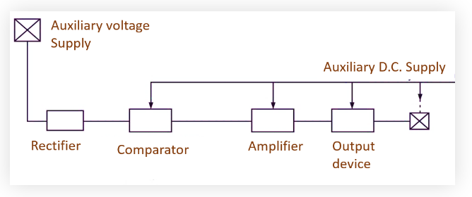
How It Works
The operation of a static relay involves a series of electronic steps:
- Sensing: A current transformer (CT) or potential transformer (PT) measures an electrical quantity (like current or voltage) from the system.
- Conversion: A rectifier circuit converts the incoming AC signal into a DC signal.
- Comparison: The DC signal is fed into a comparator, which compares its value to a predefined reference or threshold.
- Amplification: If the measured signal exceeds the threshold, the output of the comparator is amplified.
- Tripping: The amplified signal then activates an output device, which can be another relay or a direct signal to trip a circuit breaker, thereby isolating the faulty section of the electrical system.
Some static relays also include a time-delay circuit, which can be adjusted to provide a specific delay before the tripping action occurs.
Advantages and Disadvantages
Static relays have several key advantages over their electromechanical predecessors, but they also have some drawbacks.
Advantages:
- Fast Response Time: Because they don’t have moving parts, static relays can operate almost instantaneously, allowing for quick fault detection and isolation.
- High Reliability and Long Life: The absence of mechanical wear and tear means static relays are highly reliable and have a longer operational lifespan with less maintenance.
- High Sensitivity and Accuracy: Solid-state components allow for precise measurements and a wider range of operating characteristics, making them more accurate.
- Compact Size: Their electronic design allows for smaller and more compact construction.
- Low Power Consumption: Static relays consume very little power, which reduces the burden on instrument transformers.
- Immunity to Vibration and Shock: Without moving parts, they are not affected by mechanical vibrations or shocks.
Disadvantages:
- Susceptibility to Surges: The electronic components are sensitive and can be easily damaged by high voltage surges or electrostatic discharges.
- Lower Overload Capacity: They generally have a lower short-term overload capacity compared to electromechanical relays.
- Requires an Auxiliary Power Supply: The internal electronic circuits need a stable auxiliary DC power supply to operate, which adds to the overall system complexity.
- Cost: Static relays are often more expensive than their electromechanical counterparts.
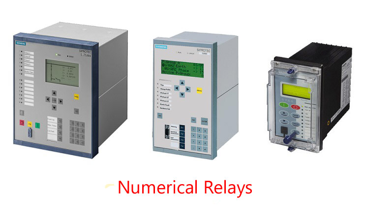
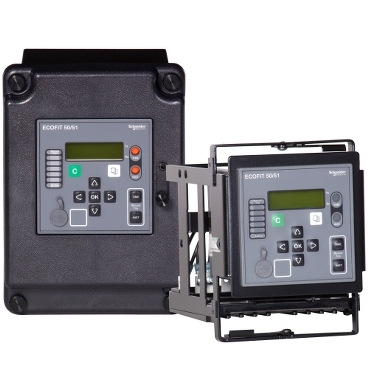
Digital/Numerical Relays:
These are microprocessor-based relays that offer high precision, flexibility, and the ability to implement complex protection schemes. They can also provide additional functionalities like fault recording and communication.
A digital or numerical relay is a modern, computer-based protective relay that uses a microprocessor to analyze electrical quantities and detect faults. Unlike electromechanical relays which use physical moving parts, or static relays which use analog electronic circuits, these relays use software-based algorithms and digital signal processing to make protection decisions. The terms “digital” and “numerical” are often used interchangeably to describe these devices.
How It Works
The operation of a digital relay involves a series of digital steps:
- Sensing: Current transformers (CTs) and potential transformers (PTs) measure the system’s current and voltage.
- Conversion: The analog signals from the CTs and PTs are passed through a low-pass filter to remove high-frequency noise and then converted into digital data by an Analog-to-Digital Converter (ADC).
- Processing: A microprocessor or digital signal processor (DSP) processes this digital data using sophisticated mathematical algorithms, such as the Fourier transform, to extract key parameters like RMS values, phase angles, and frequency.
- Decision Making: The processed data is compared against predefined settings and protection algorithms to determine if a fault condition exists.
- Tripping: If a fault is detected, the relay activates an output circuit to trip a circuit breaker, isolating the faulty section.
Advantages over Traditional Relays
Digital relays have largely replaced older technologies due to their numerous advantages:
- Flexibility and Multi-functionality: A single digital relay can perform multiple protection functions (e.g., overcurrent, overvoltage, frequency) by simply changing the software settings, making them extremely versatile.
- High Accuracy and Speed: By using digital signal processing, these relays offer precise measurements and faster response times, which is critical for minimizing equipment damage during a fault.
- Advanced Features: They come with features like event logging and fault recording, storing data about the fault to help engineers with post-fault analysis and troubleshooting.
- Communication Capabilities: Digital relays can communicate with other relays and with a central SCADA (Supervisory Control and Data Acquisition) system, enabling remote monitoring, control, and better coordination of the entire protection scheme.
- Compact Size: The use of microprocessors and integrated circuits allows for a much more compact design compared to their electromechanical predecessors.
By Function-
Overcurrent Relays (50/51):
An overcurrent relay is a type of protective relay that operates when the current in a circuit exceeds a preset, or “pickup,” value. Its primary function is to protect electrical equipment and systems from the damaging effects of excessive currents, which can be caused by faults like short circuits, ground faults, or overloads. By detecting these high current conditions, the relay triggers a circuit breaker to open and isolate the faulty section, preventing damage to the rest of the system.
How It Works
An overcurrent relay continuously monitors the current flowing through a circuit via a current transformer (CT). When the current exceeds the relay’s set threshold, the relay’s internal mechanism activates. Depending on the type of relay, this activation can be immediate or have an intentional time delay. The activation of the relay sends a signal to a circuit breaker’s trip coil, causing the breaker to open and de-energize the circuit.
Types of Overcurrent Relays
Overcurrent relays are classified based on their time-current characteristics, which determine how quickly they operate in response to an overcurrent. The main types include:
- Instantaneous Overcurrent (IOC) Relay: This type of relay operates with virtually no intentional time delay when the current exceeds its pickup value. It’s used for protecting against severe, high-magnitude faults like short circuits.
- Definite Time Overcurrent (DTOC) Relay: This relay operates after a fixed, user-adjustable time delay once the current exceeds the pickup value. The tripping time is independent of the current magnitude. This is useful for coordinating multiple relays in a system, ensuring that the relay closest to the fault operates first.
- Inverse Time Overcurrent (ITOC) Relay: The operating time of this relay is inversely proportional to the magnitude of the fault current. The higher the current, the faster it operates. This characteristic is ideal for protecting equipment that can handle a momentary overload but needs rapid disconnection for severe faults. There are several sub-types, such as:
- Inverse Definite Minimum Time (IDMT): A very common type of ITOC relay. It has an inverse time characteristic up to a certain point, after which the time becomes definite (constant) for very high currents.
- Very Inverse and Extremely Inverse: These relays have a more pronounced inverse characteristic, meaning the operating time changes more drastically with changes in current.
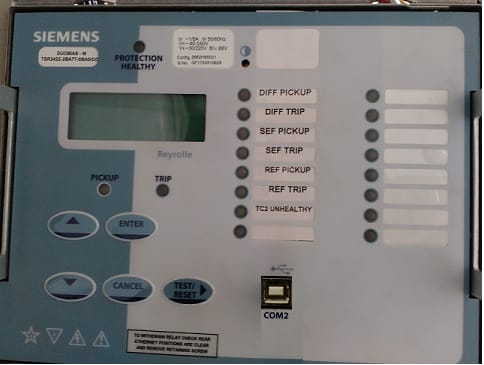
Differential Relays (87):
A differential relay is a protective device that operates based on the difference between two or more electrical quantities, most commonly current. Its purpose is to protect a specific “zone” of an electrical system, such as a generator, transformer, or busbar, from internal faults (faults that occur within the protected zone).
It does this by continuously comparing the current entering the zone with the current leaving it. These relays operate based on the difference between the current entering and leaving a protected zone. They are highly sensitive to faults within the protected zone and are commonly used for protecting transformers, generators and buses
How It Works
The working principle of a differential relay is based on Kirchhoff’s Current Law (Iin = Iout ). In a healthy system, the current entering a protected zone should be equal to the current leaving it. The relay uses current transformers (CTs) to measure the current at the input and output points of the zone. The outputs of these CTs are wired to the relay in such a way that their secondary currents oppose each other.
- Normal Conditions: Under normal load conditions, the currents at the input and output are equal, so the differential current (the difference between the two) is zero or very close to it. The relay remains inactive.
- External Fault: If a fault occurs outside the protected zone, the currents on both sides of the zone increase proportionally, but the balance is maintained. The differential current remains negligible, and the relay does not operate.
- Internal Fault: If a fault occurs inside the protected zone (e.g., a winding short circuit in a transformer), the current balance is disrupted. The current entering the zone no longer equals the current leaving it. This creates a significant differential current that flows through the relay’s operating coil. When this differential current exceeds a predefined threshold, the relay sends a trip signal to the circuit breakers, isolating the faulty equipment from the rest of the system.
Types and Applications
Differential relays are highly sensitive and selective, meaning they can detect small internal faults and will only operate for faults within their defined protection zone.
Types of Differential Relays:
- Current Differential Relay: The most common type. It directly compares the magnitude and phase of the currents on either side of the protected equipment.
- Percentage (or Biased) Differential Relay: This type adds a “restraining” coil to prevent false tripping due to minor current imbalances, such as those caused by CT saturation or magnetizing inrush currents in transformers. The relay operates only if the differential current exceeds a certain percentage of the average current flowing through the protected zone.
- High-Impedance Differential Relay: Used primarily for busbar protection, where multiple CTs are involved. It is designed to be highly stable and immune to CT saturation during external faults.
Common Applications:
- Transformer Protection: A crucial application where it protects against internal faults like winding-to-winding or winding-to-ground faults.
- Generator and Motor Protection: Used to protect stator windings from internal short circuits.
- Busbar Protection: A busbar is a critical connection point in a substation. Differential relays provide fast and reliable protection for these components.
- Feeder and Transmission Line Protection: Used to detect and isolate faults along a transmission line.
Distance Relays (21):
A distance relay is a type of protective relay that operates by measuring the impedance of an electrical circuit and comparing it to a predefined setting. These relays measure the impedance between the relay location and the fault point. Its name comes from the fact that the impedance of a transmission line is directly proportional to its length; therefore, the relay can effectively determine the “distance” to a fault.
When a fault occurs, the impedance seen by the relay decreases. If this measured impedance falls below a certain threshold, it indicates that the fault is within the relay’s designated protection zone, and the relay sends a signal to trip a circuit breaker. The operating time is proportional to this impedance, and they are primarily used for the protection of transmission lines.

How It Works
The working principle of a distance relay is based on Ohm’s Law (Z = V/I). It continuously monitors the voltage and current at its location using potential transformers (PTs) and current transformers (CTs).
- During normal operation, the ratio of voltage to current ( V/I) represents the impedance of the normal load and is high.
- During a fault, the voltage at the relay location drops significantly, while the current increases dramatically. This causes the measured impedance to decrease.
The relay’s internal mechanism compares the measured impedance to its setting, or “reach.” If the measured impedance is less than the relay’s reach, it confirms that the fault is within its protected zone and initiates the tripping sequence. The time of operation for a distance relay can be instantaneous for faults very close to it and progressively delayed for faults further away, which is a key feature for coordinating protection zones.
Types of Distance Relays
Distance relays are primarily classified based on their operating characteristics on a R-X (Resistance-Reactance) plane, a graphical representation of the impedance measured by the relay.
- Impedance Relay: This relay has a circular characteristic centered at the origin of the R-X plane. It’s a simple, non-directional relay that operates when the measured impedance falls within the circle. It is typically used for medium-length transmission lines.
- Reactance Relay: This relay’s characteristic is a straight line parallel to the resistance axis. It operates when the measured reactance is below the set value and is highly suitable for short transmission lines because its operation is largely unaffected by arc resistance at the fault location.
- Mho Relay (Admittance Relay): The mho relay has a circular characteristic that passes through the origin of the R-X plane. It is inherently directional and is widely used for long transmission lines and for protecting against phase faults. Its directional nature makes it less susceptible to tripping on power swings.
Applications and Advantages
Distance relays are an indispensable part of power system protection. Their main application is the protection of high-voltage transmission lines and distribution lines.
Advantages:
- Fast and Selective Operation: They provide high-speed protection and can precisely identify faults within their predetermined zones.
- Coordination: Their adjustable time-distance characteristics allow for easy coordination with other relays, ensuring that only the closest relay to the fault operates, which minimizes power outages.
- Insensitivity to Fault Current Magnitude: Unlike simple overcurrent relays, their operation is based on the impedance ratio, which makes them less affected by changes in source impedance or generation capacity.
- Directional Capability: Many types of distance relays are inherently directional, which is crucial for protecting looped transmission systems.
Frequency Relays (81):
A frequency relay is a protective device that monitors the frequency of a power system and initiates a response when the frequency deviates from a preset range. These relays respond to changes in the frequency of the power system and are used to protect against under-frequency and over-frequency conditions, which can occur during major system disturbances. Its main purpose is to maintain system stability and prevent damage to equipment that is sensitive to frequency changes.
How It Works
Frequency relays operate by continuously measuring the frequency of the AC power supply. In a power system, frequency is directly tied to the balance between power generation and power consumption.
- Under-frequency condition: Occurs when the load on the system exceeds the power being generated. This causes the generators to slow down, leading to a drop in frequency.
- Over-frequency condition: Occurs when generation exceeds the load, causing the generators to speed up and the frequency to rise.
When the measured frequency falls below or rises above the predetermined threshold, the relay’s internal circuitry activates. This activation triggers an output signal, which can be used to:
- Trip circuit breakers to disconnect a faulty part of the system.
- Shed non-critical loads to restore the balance between generations and load (under-frequency load shedding).
- Send a signal to control systems to adjust generator output.
Types of Frequency Relays
Frequency relays are categorized based on their specific function and how they respond to frequency changes.
- Under/Over-Frequency Relays: The most common type, these relays are designed to trip when the frequency goes below a low limit (under-frequency) or above a high limit (over-frequency). They are crucial for preventing system-wide blackouts and protecting equipment like motors and generators.
- Rate of Change of Frequency (ROCOF) Relays: These relays monitor how fast the frequency is changing, rather than just the absolute value. A rapid change in frequency can indicate a sudden and severe disturbance, such as the loss of a major generator. ROCOF relays are designed to act quickly to prevent a cascading failure.
- Under-Frequency Load Shedding Relays: These are a specific application of under-frequency relays used in large power grids. When the frequency drops to a critical level, these relays are configured to automatically disconnect or “shed” blocks of non-essential loads in a staggered fashion. This helps reduce demand and allows the system to stabilize without a full collapse.
Applications
Frequency relays are essential for ensuring the reliable operation of modern power grids. They are used in:
- Generator and motor protection: To prevent damage caused by operating at abnormal frequencies.
- Substation protection: As part of load-shedding schemes to maintain grid stability during major disturbances.
- Interconnection protection: To prevent sections of a grid from becoming unstable and spreading a fault to other connected systems.
- Microgrids and distributed generation: To ensure that local generation sources remain synchronized with the main grid.
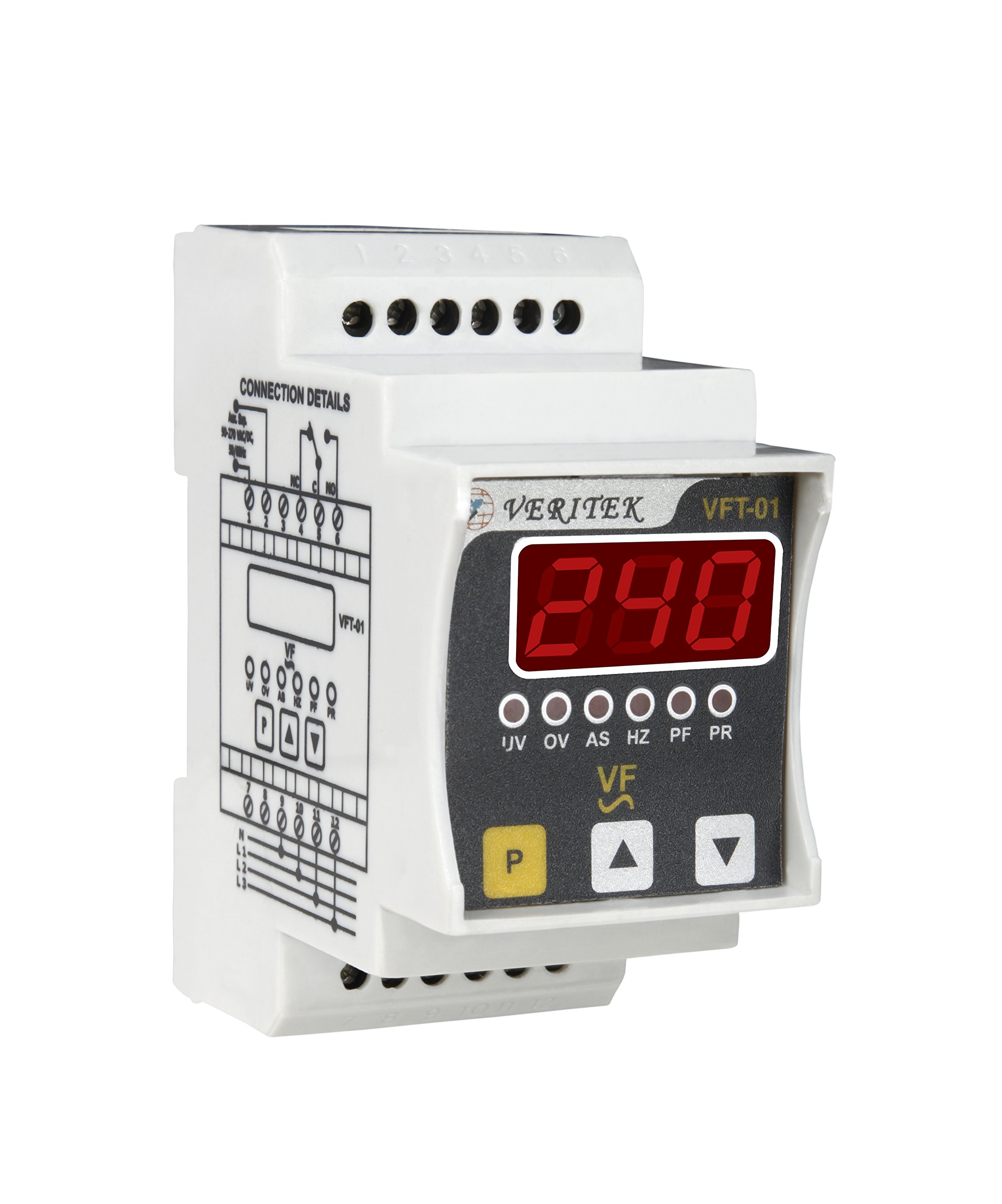
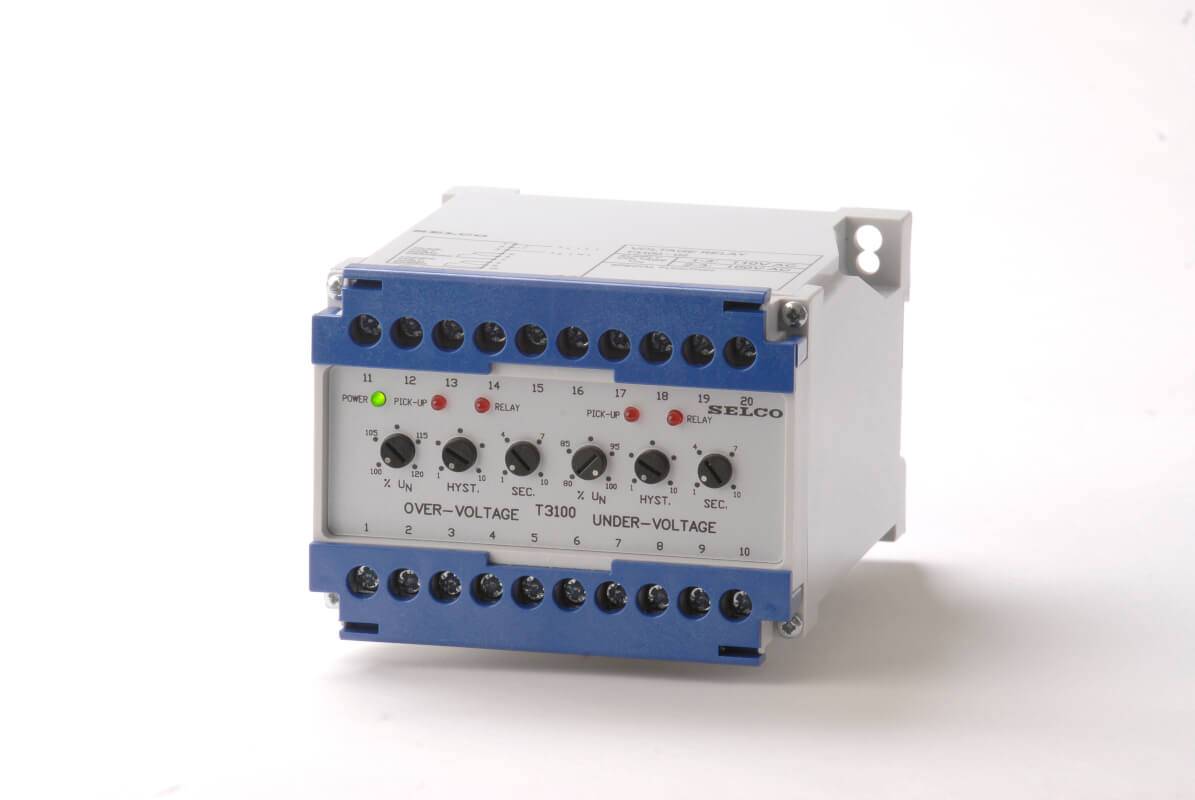
Voltage Relays:
A voltage relay is a protective device that monitors the voltage of an electrical circuit and operates when the voltage deviates from a preset, normal range. These relays operate based on the system voltage. They can be used for protection against overvoltage and under voltage conditions. Its primary function is to protect electrical equipment from damage caused by abnormal voltage conditions, such as under voltage or overvoltage.
How It Works
Voltage relays use a potential transformer (PT) to continuously measure the voltage of the system. The relay’s internal circuitry compares this measured voltage to a predefined threshold. If the voltage exceeds the overvoltage setting or drops below the undervoltage setting, the relay’s contacts activate. This activation sends a signal to a circuit breaker to open and isolate the protected equipment from the power source.
Types and Applications
Voltage relays are classified based on the voltage condition they are designed to detect. They can be found in various applications, from power generation to consumer electronics.
1. Overvoltage Relays (OVR)-[59]
These relays operate when the voltage rises above a specific limit. Overvoltage conditions can be caused by:
- Sudden loss of a large load.
- Improper tap settings on transformers.
- Faults in a power system.
- Switching surges.
OVRs are used to protect equipment that is sensitive to high voltages, such as motors, generators, and transformers.
2. Undervoltage Relays (UVR)-[27]
These relays operate when the voltage drops below a specific limit. Undervoltage conditions can be caused by:
- A fault in the power system (e.g., a short circuit).
- Starting of large motors.
- Overloading of a transformer or feeder.
UVRs are commonly used in motor protection schemes to prevent them from drawing excessive current during low-voltage conditions, which can lead to overheating and damage. They are also used for safety interlocking, ensuring that certain equipment does not start unless the voltage is within a safe operating range.
3. Over and Under-voltage Relays
Many modern relays combine both overvoltage and under-voltage protection in a single unit. An over and under-voltage relay is a protective device that monitors the voltage of an electrical circuit and operates when it goes outside of a predetermined, safe range. It combines the functions of an overvoltage relay (OVR) and an under-voltage relay (UVR) into a single unit. This type of relay is essential for protecting sensitive electrical equipment from damage caused by voltage fluctuations. These relays provide comprehensive voltage protection, monitoring both ends of the acceptable voltage spectrum.
How It Works
The relay uses a potential transformer (PT) to continuously measure the system’s voltage. Its internal circuitry compares this value to two set thresholds: a minimum for undervoltage and a maximum for overvoltage.
- Normal Operation: If the measured voltage is within the specified range (between the overvoltage and undervoltage limits), the relay remains inactive.
- Overvoltage Condition: If the voltage rises above the maximum setpoint, the relay’s overvoltage function is triggered. After a set time delay, it activates a trip circuit.
- Undervoltage Condition: If the voltage drops below the minimum setpoint, the undervoltage function is triggered. Again, after a set time delay, it activates a trip circuit.
Once a fault is detected and the time delay elapses, the relay sends a signal to a circuit breaker to open and de-energize the protected equipment, preventing potential damage. The time delay is a key feature that prevents the relay from tripping on momentary or harmless voltage spikes and dips.
Applications
These relays are widely used in a variety of applications to ensure the stability and safety of electrical systems:
- Motor Protection: Motors are particularly vulnerable to undervoltage, which can cause them to draw excessive current and overheat. These relays prevent this by tripping the circuit when the voltage drops.
- Generator Protection: Overvoltage relays are used to protect generators from high voltages that could damage their insulation.
- Transformer Protection: They are used to protect transformers from both over and undervoltage, which can lead to overheating and premature failure.
- Load Shedding: In a power grid, undervoltage relays can be used as part of a load-shedding scheme to disconnect non-critical loads during a system disturbance.
- Distribution Substations: They are a common component in substations for monitoring and protecting the distribution network.
Protective Relaying for Power X- former:
- Overcurrent Relay
- Earth Fault Relay
- Differential Relay
- Overvoltage Relay
- Undervoltage Relay
- Over fluxing Relay
- Bucholz Relay
Definite Minimum Time (DMT) Characteristics:
A DMT relay operates with a fixed time delay once the current exceeds its pickup value. The operating time is constant and does not change with the magnitude of the fault current.
- Operating Principle: If the current rises above the set threshold, the relay starts a timer. If the high current persists for the entire duration of the time setting, the relay will trip the circuit breaker.
- Characteristic Curve: The time-current characteristic of a DMT relay is a straight line parallel to the current axis.
- Application: DMT relays are often used as backup protection for distance relays and differential relays. They are also used in applications where a fixed time delay is required, regardless of the fault level.
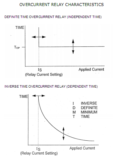
Inverse Definite Minimum Time (IDMT) Characteristics:
An IDMT relay has an operating time that is inversely proportional to the magnitude of the fault current. This means that the higher the fault current, the faster the relay will operate.
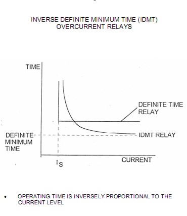
- Operating Principle: The relationship between current and operating time is designed to be inverse. For severe faults with very high currents, the relay operates very quickly. For less severe faults with lower currents, the operating time is longer.
- Characteristic Curve: The time-current characteristic of an IDMT relay is a curve where the operating time decreases as the current increases. There are several standard IDMT curves, including:
- Standard Inverse (SI)
- Very Inverse (VI)
- Extremely Inverse (EI) These curves offer different degrees of inverseness to suit various protection coordination requirements. For instance, extremely inverse curves are well-suited for protecting equipment like motors from overheating.
- Application: IDMT relays are widely used for the overcurrent protection of distribution feeders, transformers, and generators. Their inverse characteristic allows for effective coordination between multiple protective devices in a power system. For a fault far from the source, where the fault current is lower, the relay will have a longer operating time. For a fault closer to the source, with a higher fault current, the relay will operate faster. This helps in selectively isolating only the faulty section of the system.
In summary, the choice between DMT and IDMT characteristics depends on the specific requirements of the protection scheme and the equipment being protected. DMT provides a constant time delay, while IDMT offers a time-current response that is adaptable to the severity of the fault, enabling better coordination and selectivity in complex power systems.