What is clamp meter?
A clamp meter is a type of electrical testing instrument used to measure current without physically disconnecting a conductor or breaking the circuit. It has jaws (clamps) that open and close around a conductor to detect the magnetic field generated by the current flowing through it. Modern clamp meters can measure AC current, DC current, voltage, resistance, continuity and sometimes even frequency or temperature. It works on the principle of electromagnetic induction (for AC) or a Hall-effect sensor (for DC).
How to Operate a Clamp Meter (Practical Use):
Operating a clamp meter is a straightforward process designed for both safety and convenience.
Turn the dial to the correct measurement mode:
Select the Measurement Function: Turn the rotary switch on the clamp meter to the desired measurement setting. For current measurement, this is typically denoted by ‘A’ for amperes, with options for either AC (alternating current) or DC (direct current)
AC Current (A\~),
DC Current (A⎓),
Voltage (V\~ or V⎓),
Resistance (Ω), etc.
Open the Jaws:
Press the lever on the side of the meter to open the spring-loaded jaws.
Encircle the Conductor:
Place the open jaws around a single conductor (wire) through which the current you want to measure is flowing. It is crucial to clamp around only one wire. Clamping around multiple conductors will result in an inaccurate reading due to the cancellation of opposing magnetic fields. Clamp around a single conductor (not the whole cable or the currents will cancel out).
Close the Jaws:
Release the lever to allow the jaws to close completely. A secure and complete closure is essential for an accurate reading.
Read the Display:
The measured current value will be shown on the meter’s digital display. For low current measurements, some clamp meters allow you to wrap the conductor around the jaw multiple times to amplify the reading; in such cases, you must divide the displayed value by the number of turns you’ve made.
Additional Functions:
Modern clamp meters often include features found in multi-meters. These can be accessed using the rotary switch and may require the use of test leads for measuring voltage, resistance, and continuity.
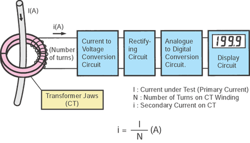
Internal Working Principle
Inside a clamp meter, the signal goes through several stages:
Current Sensing (Number of Turns):
At the heart of an AC clamp meter’s operation is the principle of a current transformer. The hinged jaws of the clamp meter are made of ferrite iron and act as the core of this transformer. The conductor carrying the current to be measured effectively becomes the primary winding, which consists of a single turn.
The secondary winding is a coil of wire with a large number of turns wrapped around the ferrite core within the clamp meter. According to the transformer principle, the current induced in the secondary winding is inversely proportional to the ratio of the number of turns in the primary and secondary windings. This relationship is expressed by the formula:
Ip×Np = Is×Ns
Where:
- Ip is the primary current (the current in the conductor).
- Np is the number of turns in the primary (which is 1).
- Is is the secondary current (the current induced in the meter’s winding).
- Ns is the number of turns in the secondary winding.
By having a large number of turns in the secondary winding (e.g., 1000 or more), the clamp meter effectively “steps down” the high current in the conductor to a much smaller, manageable level that can be easily measured by the internal circuitry. For example, a 10A current in the primary could be reduced to 10mA in the secondary
Current-to-Voltage Conversion Circuit:
The small AC current from the secondary winding of the current transformer is then converted into a proportional AC voltage. This is typically achieved using a current-to-voltage converter, often built around an operational amplifier (op-amp). This circuit provides a low-impedance path for the secondary current and outputs a voltage that is linearly related to it.
For DC current measurement, a different technology is employed: the Hall Effect sensor. This sensor is placed in a small air gap within the clamp’s jaws. When a DC current flows through the conductor, it creates a steady magnetic field that is concentrated by the ferrite core. The Hall Effect sensor, when subjected to this magnetic field, generates a voltage (the Hall voltage) that is directly proportional to the strength of the magnetic field, and thus to the DC current. This voltage output is then processed by the subsequent stages of the circuitry.
Rectifying Circuit:
For AC measurements, the AC voltage from the current-to-voltage converter must be converted into a DC voltage before it can be processed by the analog-to-digital converter. This is the role of the rectifying circuit.
To ensure accuracy, especially for low-level signals, clamp meters utilize a precision rectifier. Unlike a simple diode rectifier which has a significant voltage drop (around 0.7V), a precision rectifier circuit, also typically built with op-amps, can rectify AC signals with amplitudes much smaller than a diode’s forward voltage drop. This ensures that even small AC currents are measured accurately. The output of the precision rectifier is a DC voltage that represents the average or RMS (Root Mean Square) value of the original AC current
Analog-to-Digital Conversion (ADC):
The DC voltage from the rectifying circuit (for AC measurements) or the Hall Effect sensor (for DC measurements) is an analog signal. To be displayed on a digital screen, it must be converted into a digital value. This conversion is performed by an Analog-to-Digital Converter (ADC).
A common type of ADC used in digital multimeters and clamp meters is the integrating ADC, specifically the dual-slope integrating ADC. This type of ADC is known for its high accuracy and excellent noise rejection. The conversion process involves two phases:
- Integration Phase: The input analog voltage is integrated for a fixed period, causing the output of an integrator to ramp up.
- De-integration Phase: A known reference voltage of the opposite polarity is then applied to the integrator, causing it to ramp down. The time it takes for the integrator’s output to return to zero is measured.
The measured time is directly proportional to the input analog voltage. This digital time value is then used to drive the display. Many modern clamp meters use highly integrated ADC chips, such as the popular ICL7107 and its derivatives, which not only perform the A/D conversion but also include the logic required to drive a 3.5 or 4.5-digit seven-segment display.
5. Display Circuit:
The final stage is the display circuit, which takes the digital output from the ADC and presents it to the user in a readable format. In most modern clamp meters, this is a Liquid Crystal Display (LCD).
The display driver circuitry, which is often integrated within the ADC chip (like the ICL7107), decodes the digital value and activates the appropriate segments on the LCD to show the numerical reading. The display will also show other important information, such as the unit of measurement (A, V, Ω), the type of current (AC or DC), and any special functions that are active (e.g., hold, min/max).
The driver ensures that the correct voltages are applied to the LCD segments to make them visible.In essence, the seemingly simple act of clamping a meter around a wire initiates a complex yet elegant sequence of electronic processes. From the fundamental principles of electromagnetism to the precision of modern integrated circuits, each component plays a vital role in delivering a safe, convenient, and accurate current measurement.
Special Case — DC Current Measurement:
- AC current uses electromagnetic induction via a CT.
- DC current requires a Hall-effect sensor inside the clamp:
- It detects the magnetic field directly.
- The sensor outputs a voltage proportional to the magnetic field → amplified → sent to ADC → displayed.
Advantages:
- Non-contact current measurement → No need to cut wires.
- Safe→ User doesn’t have to touch bare conductors.
- Quick → just clamp around the wire to measure current.
Applications:
- Troubleshooting electrical systems.
- Measuring load current in motors, transformers, and panels.
- Maintenance in industrial, commercial, and residential wiring systems.