Instrument Transformers
Instrument Transformers are special-purpose transformers used in electrical power systems to measure high voltages and currents safely and accurately, and to provide electrical isolation between high-voltage circuits and measuring/protection equipment.
They step down current or voltage from high values to standardized, low, measurable values suitable for meters, relays, and other instruments.
- “Instrument transformers” are used for measuring voltage and current (where direct measurement might not be Easy/Economical) in electrical power systems.
- Generally in electrical power system voltage or current is too large to measure conveniently directly. So these are scaled down to a standardized lower value by using instrument transformers.
Types of Instrument Transformers
Instrument Transformers are classified into two types
- Current Transformer (CT)
- Voltage Transformer (VT)
Current Transformer (CT)
Purpose: Steps down high current to a standard low value (typically 5 A or 1 A).
Working Principle:
Working Principle The working principle of a Current Transformer is based on the principle of mutual electromagnetic induction, similar to a conventional power transformer. When a high alternating current flows through the primary winding, it produces an alternating magnetic flux in the core. This alternating flux links with the secondary winding and induces an electromotive force (EMF) in it, according to Faraday’s law of electromagnetic induction.
Since the secondary winding is connected to a closed circuit (the burden, which is the load of the measuring instruments or relays), the induced EMF drives a current through it. The ratio of the primary current () to the secondary current () is approximately inversely proportional to the ratio of the number of turns in the primary winding () to the number of turns in the secondary winding ():
Ip / Is ≈ Ns/ Np
This relationship is known as the turns ratio. By having a large number of turns in the secondary and a small number of turns in the primary, a high primary current can be stepped down to a low, standardized secondary current.
A crucial aspect of CT operation is that the secondary winding should never be open-circuited while the primary is energized. If the secondary is open, there is no secondary current to produce a counter-magnetic flux. This leads to an unopposed primary magneto motive force, causing the core to saturate. The rapidly changing flux induces a dangerously high voltage across the open secondary terminals, which can be a safety hazard and can also damage the CT’s insulation.
Construction
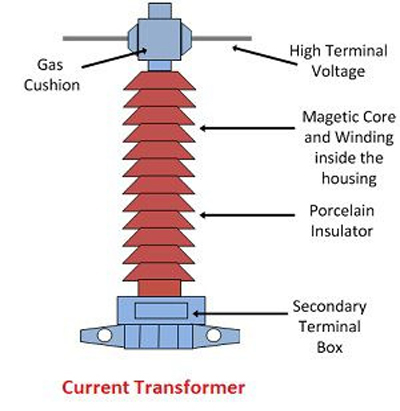
The construction of a Current Transformer is similar to a standard transformer but with some key differences tailored to its specific function. Primary winding has few turns (often just one), secondary winding has many turns. The main components include:
- Core: The core is typically made of high-permeability silicon steel laminations to minimize energy losses. It is designed to have a low reluctance path for the magnetic flux. The shape of the core can be toroidal (ring-shaped), rectangular, or in the form of a wound strip.
- Primary Winding: The primary winding is connected in series with the high-current line being measured. It consists of a very small number of turns, often just a single turn. In some types, like the “bar-type” CT, the primary conductor itself acts as the single-turn primary winding as it passes through the core’s central window.
- Secondary Winding: The secondary winding has a much larger number of turns compared to the primary. It is wound around the core and is connected to the measuring instruments or protective relays. The standard secondary current ratings are typically 1A or 5A.
- Insulation: Proper insulation is provided between the primary and secondary windings, and between the windings and the core, to withstand the high voltage of the primary circuit. The entire assembly is often enclosed in a robust casing, which can be made of resin, oil-immersed paper, or other insulating materials depending on the voltage level and application.
Advantages
Current Transformers offer several significant advantages in electrical systems:
- Safety: They provide galvanic isolation between the high-voltage primary circuit and the low-voltage secondary circuit, ensuring the safety of personnel and equipment connected to the secondary side.
- Accurate Measurement: CTs provide a highly accurate and linear transformation of current over a wide operating range, which is crucial for precise metering and effective protection.
- Standardized Output: The secondary current is standardized to 1A or 5A, allowing for the use of standard, low-range measuring instruments and relays, regardless of the primary current magnitude.
- Wide Range of Applications: They are versatile and can be used for a variety of applications, from revenue metering to complex protection schemes.
- Reliability and Durability: CTs are generally robust and have a long operational life with minimal maintenance requirements.
- Ease of Installation: Many types of CTs, especially the window or split-core types, are easy to install without the need to disconnect the primary conductor.
Disadvantages
Despite their numerous benefits, Current Transformers also have some limitations:
- Saturation: Under very high fault currents, the magnetic core of a CT can saturate. This leads to a non-linear relationship between the primary and secondary currents, causing inaccuracies in measurement and potentially affecting the performance of protective relays.
- Burden Sensitivity: The accuracy of a CT is dependent on the connected burden (the impedance of the secondary circuit). A burden higher than the rated value can lead to significant errors.
- Open Circuit Hazard: As mentioned earlier, an open-circuited secondary winding can result in extremely high voltages, posing a serious safety risk.
- Cost: High-precision and high-voltage CTs can be expensive.
- Size and Weight: High-voltage CTs can be large and heavy, requiring substantial mounting structures.
Applications:
- Measurement: Supplying reduced current to ammeters, watt meters, energy meters.
- Protection: Operating overcurrent, earth fault, differential protection relays.
- Control: Input to SCADA and automation systems.
- Testing: Used in calibration and testing of electrical equipment.
Key Point: The secondary should never be open-circuited when energized—dangerous high voltage can appear.
Types of current transformers
Based on Construction
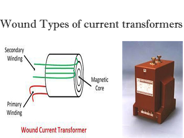
a) Wound Type CT
Construction: Primary winding has more than one turn wound on the core, similar to a normal transformer.
Use: For low-current measurement where primary current is not too high.
Example: Laboratory testing, precision metering.
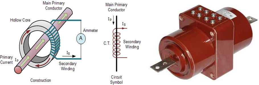
b) Bar Type CT
Construction: The primary winding is a single solid bar (busbar) passing through the core.
Use: For high-current measurements in busbars or switchgear.
Feature: Very robust and used in substations.
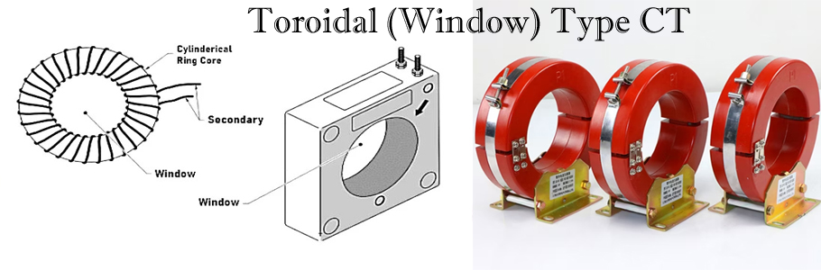
c) Toroidal (Window) Type CT
Construction: No separate primary winding; the conductor carrying the current passes through the CT’s window.
Use: Retrofitting on existing conductors without disconnecting the circuit.
Example: Residual Current Devices (RCDs), Earth Fault Protection.
Based on Application
A) Measuring CT
Purpose: For operating measuring instruments (ammeters, energy meters).
Accuracy Classes: 0.1, 0.2, 0.5, 1.0, etc.
Burden: Low (few VA).
B) Protective CT
Purpose: For operating protective relays during abnormal or fault conditions.
Accuracy Classes: 5P, 10P (Protection class).
Feature: Can handle high saturation currents during faults.
C) Special Purpose CT
Examples:
- Summation CT: Combines currents from several circuits.
- Differential Protection CT: For generator, transformer, or motor differential protection schemes.
- Split-core CT: For temporary or clamp-on measurements.
Potential Transformer (PT)
(Also called Voltage Transformer, VT)
Purpose: Steps down high voltage to a standard low value (e.g., 110 V or 63.5 V).
Construction:
Similar to a power transformer but optimized for accuracy at low loads. The key components include:
- Core: The core is constructed from high-quality, low-loss silicon steel laminations. This minimizes magnetizing current and reduces core losses, which is essential for maintaining high accuracy. Both core-type and shell-type constructions are used.
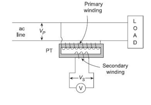
- Primary Winding: This winding consists of a large number of turns of fine wire and is connected in parallel with the high-voltage circuit whose voltage is to be measured or monitored.
- Secondary Winding: This winding has significantly fewer turns compared to the primary winding. It is wound on the same core as the primary and provides the stepped-down voltage. The standard secondary voltage is typically 110 V or 120 V.
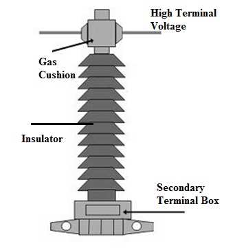
- Insulation: Due to its connection to high-voltage lines, insulation is a critical aspect of PT design. High-quality insulation materials like oil-impregnated paper, varnish, and porcelain are used between the windings, and between the windings and the core, to withstand the high potential.
- Bushings: To connect the high-voltage primary winding to the power line, porcelain bushings are used. These provide a well-insulated and secure terminal point. For safety, one end of the secondary winding is always grounded.
Working Principle
The working principle of a Potential Transformer is based on mutual electromagnetic induction, the same principle that governs a standard transformer.
When the primary winding is connected across the high-voltage line, an alternating current starts to flow through it. This current produces an alternating magnetic flux in the core. According to Faraday’s Law of Electromagnetic Induction, this changing magnetic flux induces an electromotive force (EMF) in both the primary and secondary windings.
Since the secondary winding is connected to a high-impedance load (like a voltmeter or the voltage coil of a relay), it draws a very small current. The voltage transformation ratio is determined by the turns ratio of the primary () and secondary () windings:

By having a large number of turns on the primary and a small number of turns on the secondary, the PT accurately steps down the high voltage to a safe and measurable level at the secondary terminals.
Based on their design, there are two main types of Potential Transformers:
- Conventional Wound Type (Electromagnetic): These are similar to standard transformers with primary and secondary windings on a magnetic core. They are highly accurate and used for a wide range of voltages.
- Capacitor Voltage Transformer (CVT) or Capacitor Coupled Potential Transformer (CCPT): Used for very high voltages (above 100 kV), these transformers use a series of capacitors in a potential divider arrangement to initially step down the voltage to an intermediate level (e.g., 10-20 kV). This intermediate voltage is then further stepped down by a smaller, conventional electromagnetic transformer.
Advantages
Potential Transformers offer several key advantages in power systems:
- Safety: They provide galvanic isolation between the high-voltage power circuit and the low-voltage measuring and protection instruments, ensuring the safety of personnel and equipment.
- Accurate Measurement: PTs are designed for high accuracy, allowing for precise voltage measurement which is crucial for billing, system control, and performance analysis.
- Standardized Secondary Voltage: The output voltage is stepped down to a standard low level (e.g., 110 V), which allows for the use of standard, readily available, and less expensive measuring instruments and relays.
- Feasibility of Measurement: They make it possible to measure very high voltages that would otherwise be impossible to measure with standard voltmeters.
- Protection of Instruments: By isolating them from the high-voltage line, PTs protect sensitive measuring and protection devices from potential damage due to high voltages.
Disadvantages
Despite their benefits, Potential Transformers also have some limitations:
- Voltage and Phase Angle Errors: In practice, due to the winding resistances and reactance’s, the voltage ratio is not exactly equal to the turns ratio, leading to a small voltage error. Also, there is a slight phase shift between the primary voltage and the reversed secondary voltage, known as the phase angle error. These errors can affect the accuracy of measurements, especially for precision metering.
- Burden Sensitivity: The accuracy of a PT is dependent on the connected load, known as the “burden.” If the burden exceeds the rated value, the errors in voltage and phase angle can increase significantly.
- Limited Power Rating: PTs are not designed to supply power; they have a very low VA (Volt-Ampere) rating, sufficient only to operate the connected measuring and protection devices.
- Cost and Size: High-voltage Potential Transformers can be large, heavy, and expensive due to the extensive insulation required.
Applications:
- Measurement: Supplies reduced voltage to voltmeters, watt meters, and energy meters.
- Protection: Feeds protective relays such as overvoltage, under voltage, distance relays.
- Control & Monitoring: Provides voltage signals for SCADA and automation systems.
- EHV Systems: CVTs used in place of PTs for voltages above 66 kV and for Power Line Carrier Communication (PLCC).
Key Point: Designed for high accuracy at small burdens (load on secondary).
Types of Potential Transformers (PTs)
Based on Construction
a) Electromagnetic Type PT
- Construction: Works like a small power transformer, with laminated steel core and windings.
- Voltage Range: Generally used up to around **11 kV** (sometimes up to 33 kV).
- Features:
- `High accuracy for metering and protection
- Economical for medium-voltage systems
b) Capacitive Voltage Transformer (CVT
- Construction: Uses a capacitive voltage divider to reduce high voltage to an intermediate value, then a transformer for final step-down.
- Voltage Range: Common for 66 kV and above
- Features:
- Economical for extra high voltage (EHV) transmission
- Can be used for power line carrier communication (PLCC)
- Advantages: Lighter, cheaper, and easier to insulate compared to electromagnetic PTs at high voltage.
Based on Application
a) Measuring PT
- Purpose: Supplies accurate reduced voltage to measuring instruments (voltmeters, energy meters).
- Accuracy Classes: 0.1, 0.2, 0.5, 1.0 (high precision).
b) Protective PT
- Purpose: Supplies reduced voltage to protective relays during abnormal/fault conditions.
- Accuracy Classes: 3P, 6P (designed to maintain accuracy under transient conditions).
Based on function and accuracy Potential Transformers (PTs) are classified into two main types-
- Metering Potential Transformers
- Protection Potential Transformers
1. Metering Potential Transformers
Metering PTs are used for measurement and revenue purposes. Their primary function is to provide a highly accurate voltage signal to measuring instruments like energy meters, voltmeters, and watt meters. They are designed for extremely high accuracy within a narrow, normal operating voltage range (typically 80% to 120% of the rated voltage). The focus is on minimizing both voltage error and phase angle error to ensure accurate energy calculation. During an over voltage condition (like a system fault), the core of a metering PT is designed to saturate. This saturation protects the connected delicate measuring instruments from the damaging effects of high voltage by limiting the voltage transferred to the secondary side.
The accuracy class for metering PTs is designated by numbers such as 0.1, 0.2, 0.5, and 1.0. This number represents the maximum permissible percentage voltage error at the rated voltage. For example, a Class 0.2 PT has a maximum error of .
2. Protection Potential Transformers
Protection PTs are used to operate protective relays. Their main job is to reliably reflect the system voltage to relays during both normal and fault conditions. o provide a reliable voltage signal to protective devices like distance relays, directional relays, overvoltage/undervoltage relays, etc.
The primary requirement for a protection PT is reliability, not absolute precision. It must maintain a reasonable level of accuracy over a much wider range of voltages, especially during faults. It needs to accurately reproduce the voltage up to a certain multiple of its rated value so the relay can correctly assess the fault condition. This capability is defined by its Voltage Factor (VF).
Unlike metering PTs, protection PTs are designed not to saturate for voltages up to their rated voltage factor. For instance, a protection PT might be designed to remain accurate up to 190% of its rated voltage for a short duration. This ensures the protective relay gets a true picture of the fault voltage to operate correctly.
The accuracy class for protection PTs is designated with a number followed by the letter “P,” for example, 3P or 6P. The number indicates the maximum percentage voltage error, while ‘P’ stands for Protection. For example, a Class 3P PT guarantees that its error will not exceed under specified conditions.
Special Variants
- Capacitive Voltage Transformer (CVT): Uses capacitors and a step-down transformer; often for high-voltage transmission systems.
- Optical Current Transformer (OCT): Uses optical sensors instead of electromagnetic windings.
Advantages:
- Safe isolation between high-voltage system and measuring instruments.
- Standardized secondary outputs (5 A, 1 A for CTs; 110 V for PTs).
- Higher accuracy in measurement.
- Enables use of economical, low-rating meters and relays.
Applications:
- Electrical metering and billing.
- Power system protection (fault detection, relaying).
- Power quality monitoring.
- SCADA system data acquisition
Written (descriptive) questions with answers on Instrument Transformers that are highly important for competitive exams.
Question-1. What is an instrument transformer?
Answer: An instrument transformer is a special-purpose transformer used to step down high current or voltage to a safe, standardized value for measurement, protection, and control, while providing isolation between high-voltage circuits and measuring devices.
Question-2. What are the two main types of instrument transformers?
Answer: 1. Current Transformer (CT) – steps down high current to low current (e.g., 5 A or 1 A).
- Potential Transformer (PT) – steps down high voltage to low voltage (e.g., 110 V or 63.5 V).
Question-3. Why should the secondary of a CT never be open-circuited?
Answer: If a CT’s secondary is open when energized, dangerously high voltage will be induced, which can damage equipment and pose a safety hazard.
Question- 4. Why is the secondary of a PT grounded?
Answer: Grounding one side of the PT secondary prevents insulation failure and reduces shock hazards for operators.
Question-5. What is the standard secondary rating of a CT?
Answer: The standard secondary current ratings are 5 A or 1 A at rated primary current.
Question-6. What is the standard secondary rating of a PT?
Answer: The standard secondary voltage ratings are 110 V (phase-to-phase) or 63.5 V (phase-to-neutral).
Question-7. Name the main construction types of CTs.
Answer: 1. Wound type CT – multiple primary turns, used for low current measurement.
- Bar type CT – single solid bar as primary, used for high currents.
- Toroidal type CT – no dedicated primary winding, conductor passes through core.
Question-8. Name the main types of PTs.
Answer: 1. Electromagnetic PT – conventional transformer type, used up to 33 kV.
- Capacitive Voltage Transformer (CVT) – used for 66 kV and above.
Question-9. What is the difference between a measuring CT and a protective CT?
Answer:
Measuring CT: Accurate under normal load currents, for meters.
Protective CT: Accurate during fault currents, for relays.
Question-10. What is the burden of an instrument transformer?
Answer: The burden is the load connected to the secondary, expressed in VA at rated secondary current.
Question-11. What is ratio error in a CT or PT?
Answer: Ratio error is the percentage difference between the actual transformation ratio and the nominal (rated) ratio.
Question-12. What is phase angle error in an instrument transformer?
Answer: It is the angular difference between the secondary output phasor and the reversed primary input phasor, affecting power factor measurement accuracy.
Question-13. What is a CVT and why is it used?
Answer: A Capacitive Voltage Transformer uses a capacitive voltage divider and a transformer to step down EHV voltages economically. It’s also used for Power Line Carrier Communication (PLCC).
Question-14. What is the knee point voltage in a CT?
Answer: It is the voltage at which a 10% increase in excitation voltage causes a 50% increase in excitation current, important for protection CT performance.
Question-15. What is a summation CT?
Answer: A CT that combines currents from several circuits into a single output for measurement or protection.
Question-16. What are the accuracy classes for measuring CTs?
Answer: Common accuracy classes: **0.1, 0.2, 0.5, 1.0, 3.0** — indicating percentage ratio error at rated burden.
Question-17. What are the accuracy classes for protection CTs?
Answer: Common classes: 5P, 10P, where “P” stands for protection, and the number denotes ratio error in percentage at rated conditions.
Question-18. Why are CT and PT secondary windings designed for low burden?
Answer: To maintain accuracy and reduce voltage drop across the secondary circuit.
Question-19. What is an optical current transformer?
Answer: A CT that uses optical sensing technology to measure current without magnetic cores, suitable for high-voltage applications.
Question-20. State two advantages of instrument transformers.
Answer: 1. Safe isolation between high-voltage system and measuring devices.
- Use of standardized, economical low-rating meters and relays.
MCQ:
- The main purpose of an instrument transformer is:
- A) To increase power
- B) To step down voltage or current for measurement
- C) To regulate frequency
- D) To improve power factor
✅ Answer:B
- In a Current Transformer (CT), the secondary should never be:
- A) Short-circuited
- B) Open-circuited
- C) Loaded
- D) Grounded
✅ Answer: B
- Standard secondary current ratings of CTs are:
- A) 1 A or 5 A
- B) 11 A or 15 A
- C) 10 A or 50 A
- D) 2 A or 4 A
✅ Answer: A
- Standard secondary voltage ratings of PTs are:
- A) 6.6 kV
- B) 110 V or 63.5 V
- C) 1 kV
- D) 230 V
✅ Answer: B
- Accuracy class 5P10 of a CT means:
- A) 5% accuracy up to 10 times rated current for protection
- B) 10% accuracy at full load
- C) 5% accuracy for metering
- D) 10% accuracy at no load
✅ Answer: A
- A PT is connected in:
- A) Series with the circuit
- B) Parallel with the circuit
- C) Series-parallel combination
- D) None of the above
✅ Answer: B
- A CT is connected in:
- A) Series with the load
- B) Parallel with the load
- C) Series-parallel combination
- D) Across a PT
✅ Answer: A
- The burden of an instrument transformer refers to:
- A) Power loss in primary winding
- B) Load connected to the secondary
- C) Core loss
- D) Current ratio error
✅ Answer: B
- Which type of PT is economical for voltages above 66 kV?
- A) Electromagnetic PT
- B) Auto transformer
- C) CVT
- D) Step-down transformer
✅ Answer: C
- In a bar-type CT, the primary winding consists of:
- A) Many turns of fine wire
- B) A single solid bar or busbar
- C) A hollow conductor
- D) Laminated steel strips
✅ Answer: B
- A wound type CT is preferred when:
- A) Primary current is very high
- B) Primary current is low
- C) High frequency operation is needed
- D) None of these
✅ Answer: B
- The ratio error in a CT is due to:
- A) Leakage reactance
- B) Exciting current and winding resistance
- C) Eddy currents
- D) All of the above
✅ Answer: D
- In a measuring CT, accuracy classes like 0.2, 0.5 refer to:
- A) Percentage voltage drop
- B) Percentage ratio error
- C) Copper loss
- D) Core flux
✅ Answer: B
- The rated burden of a PT is expressed in:
- A) Ohms
- B) VA
- C) Watts
- D) Volts
✅ Answer: B
- Why is the secondary of a PT one side grounded?
- A) For improved efficiency
- B) To avoid shock hazards and insulation failure
- C) To increase accuracy
- D) To reduce load
✅ Answer: B
- In a CVT, the intermediate voltage is obtained using:
- A) Inductive divider
- B) Resistive divider
- C) Capacitive divider
- D) Magnetic amplifier
✅ Answer: C
- Which one is NOT an advantage of an instrument transformer?
- A) Safety for operators
- B) Standardized meter ratings
- C) Works at both AC and DC
- D) Electrical isolation
✅ Answer: C
- For EHV transmission line voltage measurement, which is preferred?
- A) CVT
- B) Electromagnetic PT
- C) Auto transformer
- D) Isolation transformer
✅ Answer: A
- The knee point voltage in a CT is important for:
- A) Voltage measurement
- B) Differential protection accuracy
- C) Reducing copper losses
- D) Meter calibration
✅ Answer: B
- The purpose of an Optical Current Transformer is:
- A) Measure only DC current
- B) Use light signals for current measurement at high voltages
- C) Increase accuracy of induction type meters
- D) Reduce core losses
✅ Answer: B